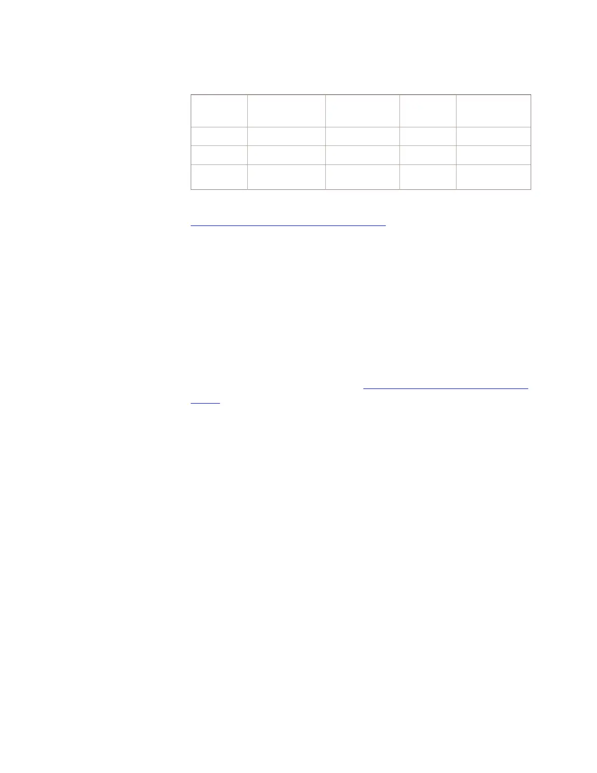
Table 2-4 PSU2 shelf power terminations (continued)
Power
Bus
Shelf EQLs
Powered
Slots Fuse
Value
Back Plane
Termination
B 100-120 PSUCOM 1 10 amp 02-108-006
B 128-152 PH 8-11 10 amp 02-134-006
B 160-184 PH 12-15 10 amp 02-166-006
The PHs should be spread across power buses and fuses. Refer to
Chapter 4, “Engineering Considerations” for more specific
recommendations.
Cabling
Ethernet cables provide the connection between the LLE2 paddle
boards (located on the back plane of the unit) and the layer 2 switch
or router. The location of each LLE2 paddle board is dependent on the
equipage of the SIP PHs. The physical connection is by a Category 5
cable with RJ-45 connectors. The maximum length of an Ethernet
100BaseT cable is 328 feet.
Connecting circuits
This section provides a brief description of the interfaces that connect
to the SIP PH and GQPH. Refer to Figure 2-16, “Connecting circuits”
(2-29).
SIP PH and GQPH interfaces consist of the following which are part
of the PSU2 back plane:
• packet bus (PB),
• control bus (CB), and
• protocol handler data bus (PHDB).
The packet bus provides the packet data interface between the PHs
and the packet fanout 2 (PF2). The PHs transmit and receive data
packets over the packet bus.
The function of the control bus is to fanout control signals, which are
controlled by the CF2, to the PHs and provide PH error status.
The protocol handler data bus provides a data interface between the
PHs and the DF2. The PHDB carries time slots between the PH and
DF2. The SIP PH does not use the PHDB.
Hardware View
Architecture
....................................................................................................................................................................................................................................
2-28
Lucent Technologies 235-200-118
Issue 3.02B, March 2007