IP Router & Layer 2
Switch Interoperability
The 5ESS
®
switch can interface with a number of IP network
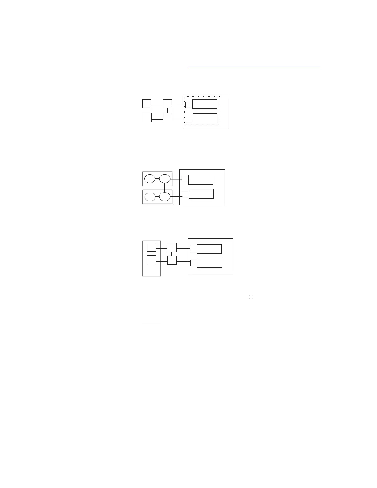
configurations. Figure 2-9, “Sample Configurations” (2-15) provides
some examples of configurations that may be used.
The configuration shown in example “a”, uses a pair of layer 2
switches along with a separate pair of routers. This configuration can
be used in cases where the routers used cannot support the layer 2
functionality. When used with the SCTP capability to support multiple
IP paths, as well as with the SIP PH’s ability to monitor the status of
Figure 2-9 Sample Configurations
Legend
R access router
L2 Layer 2 switch
E Ethernet link
SIP PH SIP protocol handler
PSU2 Packet Switching Unit 2
VRRP Virtual Router Redundancy Protocol
( a ) Separate pairs of L2 switches
and IP routers, SIP PH/Ethernet
are a serving/non-serving pair.
( b ) Integrated pair of L2 switches
and IP routers.
( c ) VRRP pair providing access routing function,
plus physical L2 switches (VRRP pair appears
as a single IP router to the 5ESS switch).
R
R
L2
E
SIP PH
P
S
U
2
E
SIP PH
R
L2
VRRP
Pair
E
SIP PH
P
R
L2
S
U
2
E
SIP PH
R
L2
E
SIP PH
P
R
L2
S
U
2
E
SIP PH
R
L2
System View
Architecture
....................................................................................................................................................................................................................................
235-200-118
Issue 3.02B, March 2007
Lucent Technologies
2-15