_ENCD – Encoder Subject area • 43Parameter Description MC6000/7000
_ENCD
_VAL
Index
_VFCON
_PMOD
_KPAD
Contents
Introduction
_SIO
_SCTY
_REF
_SYS
_IO1
_IO2
_CAN
_OPT1
_MOT
_CONF
_TCON
_SCON
_PCON
13-ECSLN - Lines per revolution in encoder simulation
Source: Encoder Simulation Line Count
Function: Parameter only for MC7000 with setting ECSIM = 1-X.
Lines per revolution in encoder simulation
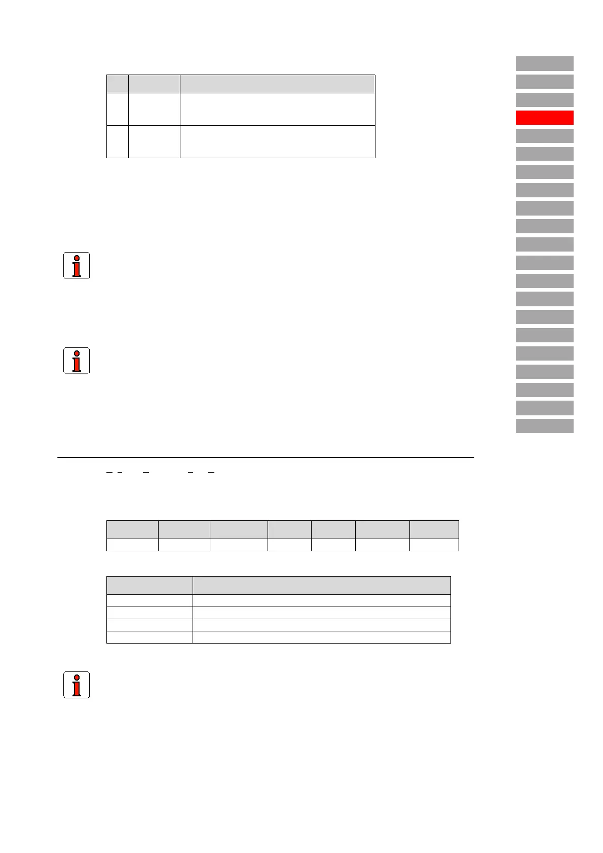
No. Setting Function
01 - 1Factory setting for optical encoders: Hardware
encoder simulation, lines per revolution = lines per
revolution of connected encoder. 1)
11 - XFactory setting for resolvers: Normal encoder sim-
ulation, lines per revolution determined by parameter
ECSLN. 1) + 2)
1) The position of the zero pulse relative to the rotor position is reproducible.
2) Only for G1 encoders: The position of the zero pulse relative to the rotor position is no longer
reproducible after a restart (referencing required). The setting 1-X is therefore usable only to a
limited extent for G1 encoders.
Note:
The encoder simulation delivers valid signals right from power-up (as from software
version V1.45). When the "S_RDY: Servocontroller ready" state is reached, the
encoder simulation signals follow the actual position of the axle. The "S_RDY" state
can be delivered via an output (see Functions for outputs on MC7000).
Note:
In the case of optical encoders and ECSIM = 1 - X no additional encoder can be
evaluated.
Values:
Minimum Maximum Factory set. Unit MODE SMARTCARD Type
128 4096 1024 – R4W4 OPTN2 USIGN8
Encoder type Lines per revolution with ECSIM = 1-X
R1 128, 256, 512, 1024, 2048, 4096
R2 256, 512, 1024, 2048, 4096, 8192
R8 384, 768, 1536, 3072, 6144, 12288
G1, G3, G5 256, 512, 1024, 2048, 4096, 8192
Note:
In the case of resolvers the delivered lines per revolution results from multiplication of
parameter ECSLN with the number of pole pairs p.