214323 136 Revision B
Figure 4.9: Measuring Voltage at Float Indicator Box
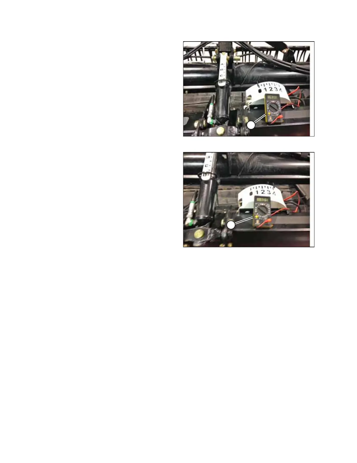
4. Using voltmeter (A), measure the voltage between ground
(Pin 2) and signal (Pin 3) wires at the AHHC sensor in the
float indicator box. Ensure it is at the high voltage limit for
the combine. For instructions, refer to Table 4.1, page 134.
NOTE:
The harness connector must be plugged into the sensor.
Figure 4.10: Measuring Voltage at Float Indicator Box
5. Fully lower the combine feeder house, and float the header
up off the down stops (the float indicator should be at 4,
and the adapter should be fully separated from the
header).
NOTE:
You may need to hold down the HEADER DOWN switch for
a few seconds to ensure feeder house is fully lowered.
6. Using voltmeter (A), measure the voltage between the
ground and signal wires at the AHHC sensor in the float
indicator box. It should be at the low voltage limit for the
combine. For instructions, refer to Table 4.1, page 134.
NOTE:
The harness connector must be plugged into the sensor.
7. Adjust the voltage limits (refer to 4.4.2 Adjusting Voltage
Limits, page 137) if the sensor voltage is not within the low
and high limits, or if the range between the low and high
limits is insufficient. For sensor voltage limits, refer to Table
4.1, page 134 .
AUTO HEADER HEIGHT CONTROL