214323 501 Revision B
1. Shut down the combine, and remove the key from the ignition.
2. Remove the drive cover. Refer to Removing Reel Drive Cover, page 488.
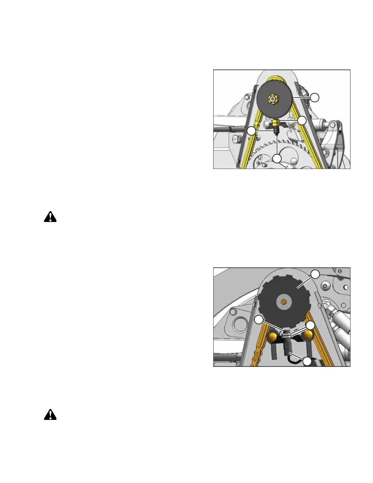
Figure 6.316: Speed Sensor
3. Disconnect electrical connector (D).
4. Remove top nut (C) and remove sensor (B).
5. Remove the top nut from the new sensor and position the
sensor into the support. Secure with top nut (C).
6. Adjust the gap between sensor disc (A) and sensor (B) to 3
mm (1/8 in.) using nut (C).
7. Connect to harness at location (D).
IMPORTANT:
Ensure the sensor electrical harness does NOT contact the
chain or sprocket.
8. Reinstall the drive cover. Refer to Installing Reel Drive
Cover, page 489.
Replacing CLAAS 400 Series Sensor
DANGER
To prevent bodily injury or death from the unexpected start-up or fall of a raised machine, always stop the engine,
remove the key, and engage the safety props before going under the header for any reason.
1. Shut down the combine, and remove the key from the ignition.
2. Remove the drive cover. Refer to Removing Reel Drive Cover, page 488.
Figure 6.317: Speed Sensor
3. Disconnect electrical connector (C).
4. Remove top nuts (D) and remove sensor (B).
5. Remove the top nut from the new sensor and position the
sensor into the support. Secure with top nut (D).
6. Adjust the gap between sensor disc (A) and sensor (B) to 3
mm (1/8 in.) using nuts (D).
7. Connect to harness at location (C).
IMPORTANT:
Ensure the sensor electrical harness does NOT contact the
chain or sprocket.
8. Reinstall the drive cover. Refer to Installing Reel Drive
Cover, page 489.
Replacing CLAAS 500/700 Series Sensor
DANGER
To prevent bodily injury or death from the unexpected start-up or fall of a raised machine, always stop the engine,
remove the key, and engage the safety props before going under the header for any reason.
MAINTENANCE AND SERVICING