214323 500 Revision B
Figure 6.313: Electrical Harness
3. Disconnect electrical connector (A).
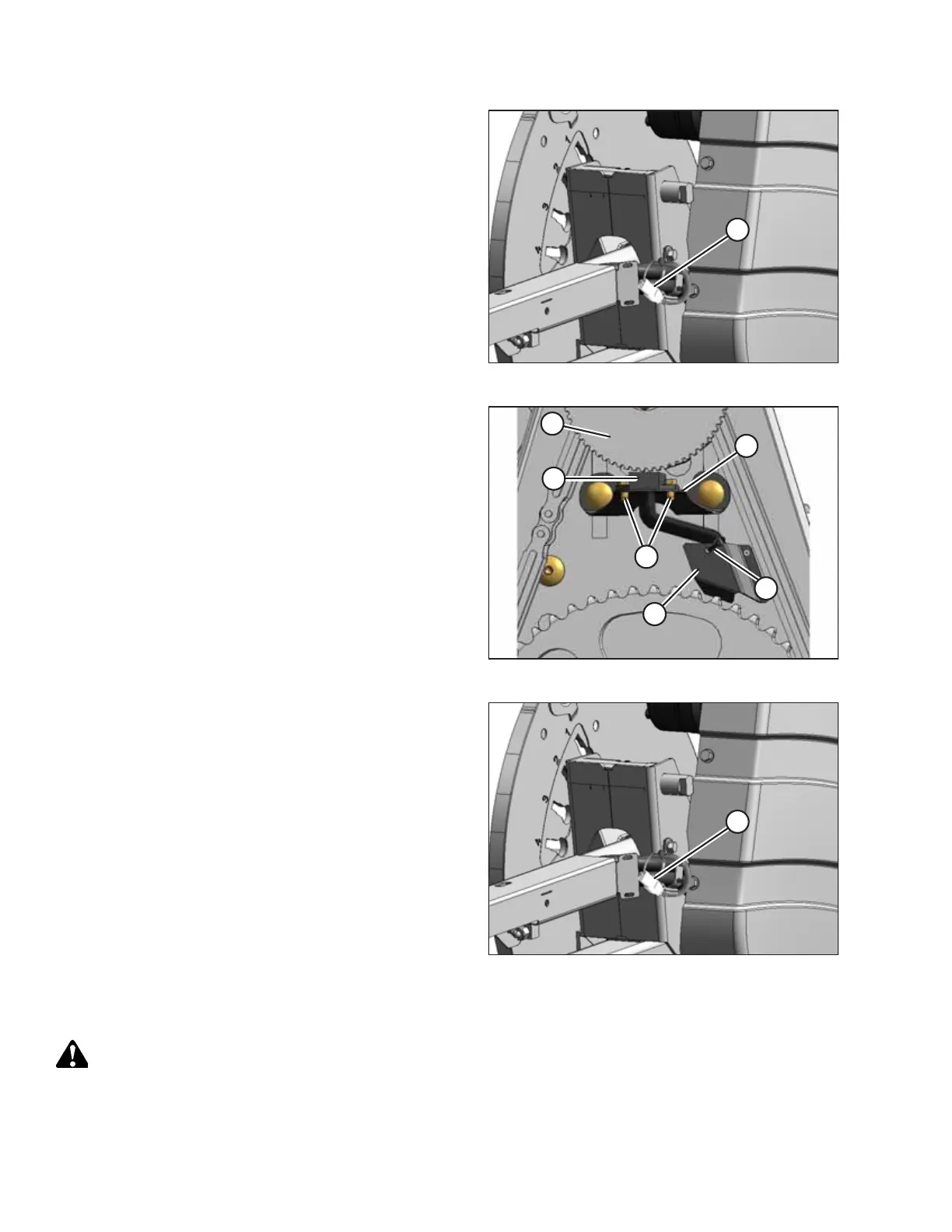
Figure 6.314: Speed Sensor
4. Cut cable tie (A) securing the harness to the cover.
5. Remove two screws (B) and remove sensor (C) and harness.
Bend cover (D) (if necessary) to remove the harness.
6. Feed the wire of the new sensor behind cover (D) and
through the chain case.
7. Locate the new sensor in support (E) and attach with two
screws (B).
8. Adjust the gap between sensor disc (F) and sensor (C) to 0.5
mm (0.02 in.).
Figure 6.315: Electrical Harness
9. Connect electrical harness (A).
IMPORTANT:
Ensure the sensor electrical harness does NOT contact the
chain or sprocket.
10. Reinstall the drive cover. Refer to Installing Reel Drive
Cover, page 489.
Replacing John Deere Sensor
DANGER
To prevent bodily injury or death from the unexpected start-up or fall of a raised machine, always stop the engine,
remove the key, and engage the safety props before going under the header for any reason.
MAINTENANCE AND SERVICING