214323 302 Revision B
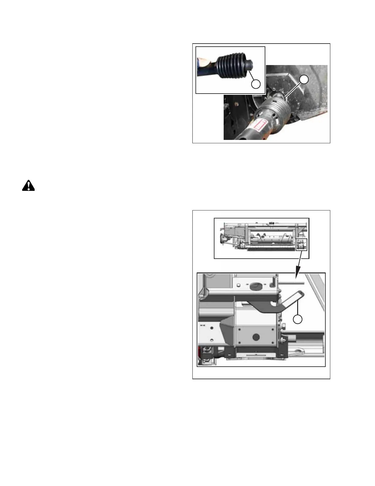
Figure 5.30: Driveline
16. Pull back collar (A) on end of the driveline, and push the
driveline onto combine output shaft (B) until the
collar locks.
5.3.2 Detaching Header from Challenger
®
, Gleaner
®
, or Massey Ferguson
®
Combine
DANGER
To prevent bodily injury or death from the unexpected start-up or fall of a raised machine, always stop the engine,
remove the key, and engage the safety props before going under the header for any reason.
Figure 5.31: Float Locked
1. Ensure that the combine is on level ground, and position
the header slightly above the ground.
2. Shut down the engine, and remove the key from the
ignition.
IMPORTANT:
If the slow speed transport wheels are installed, the header
may be detached in either transport or field mode. If
detaching with the wheels in field mode, set the wheels to
the storage or uppermost working position, otherwise, the
header may tilt forward, making reattachment difficult.
Refer to 3.7.1 Cutting Height, page 54.
IMPORTANT:
If the stabilizer wheels are installed, set the wheels to the
storage or uppermost working position; otherwise, the
header may tilt forward, making reattachment difficult.
Refer to 3.7.1 Cutting Height, page 54.
3. Engage both float locks by lifting each lock lever (A)
upwards until they latch into the LOCK position.
HEADER ATTACHMENT/DETACHMENT