214323 380 Revision B
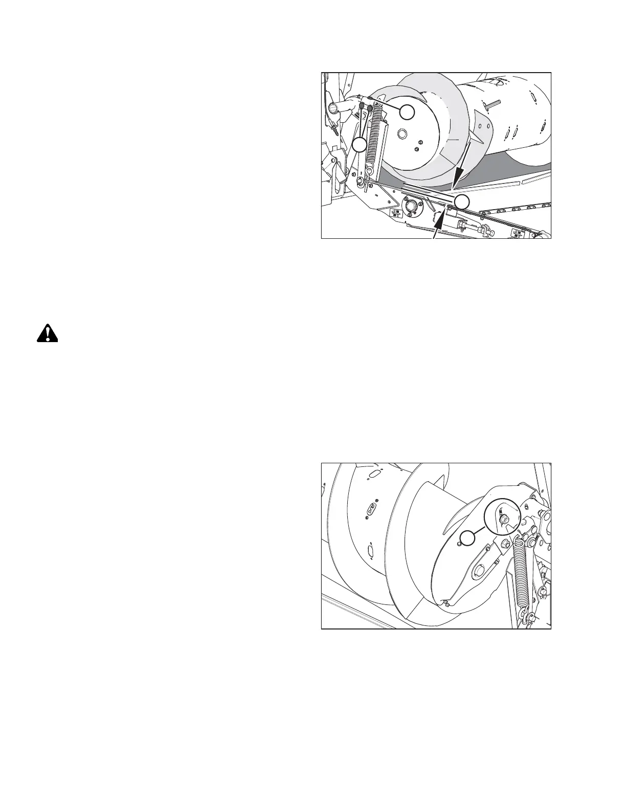
Figure 6.56: Auger Clearance
6. Loosen two nuts (B).
7. Use adjuster bolt (A) to set clearance (C) to 5–10 mm
(3/16–3/8 in.). Turn adjuster bolt (A) clockwise to increase
clearance and counterclockwise to decrease clearance.
NOTE:
The clearance increases 25–40 mm (1 – 1 1/2 in.) when
center-link is fully retracted.
8. Repeat Steps 6, page 380 and 7, page 380 on opposite end
of the auger.
9. Torque nuts (B) to 106–118 Nm (79–87 lbf·ft).
6.7.2 Checking Auger Drive Chain Tension
The auger is chain-driven by the adapter drive system sprocket attached to the side of the auger.
DANGER
To prevent bodily injury or death from the unexpected start-up of the machine, always stop the engine and remove the
key from the ignition before leaving the operator’s seat for any reason.
1. Lower the header to the ground.
2. Raise the reel fully.
3. Shut down the engine, and remove the key from the ignition.
4. Engage the reel safety props. For instructions, refer to Engaging Reel Safety Props, page 31.
Figure 6.57: Auger Drive Chain Inspection Location
5. Inspect the auger drive chain through adjustment slot (A).
MAINTENANCE AND SERVICING