214323 395 Revision B
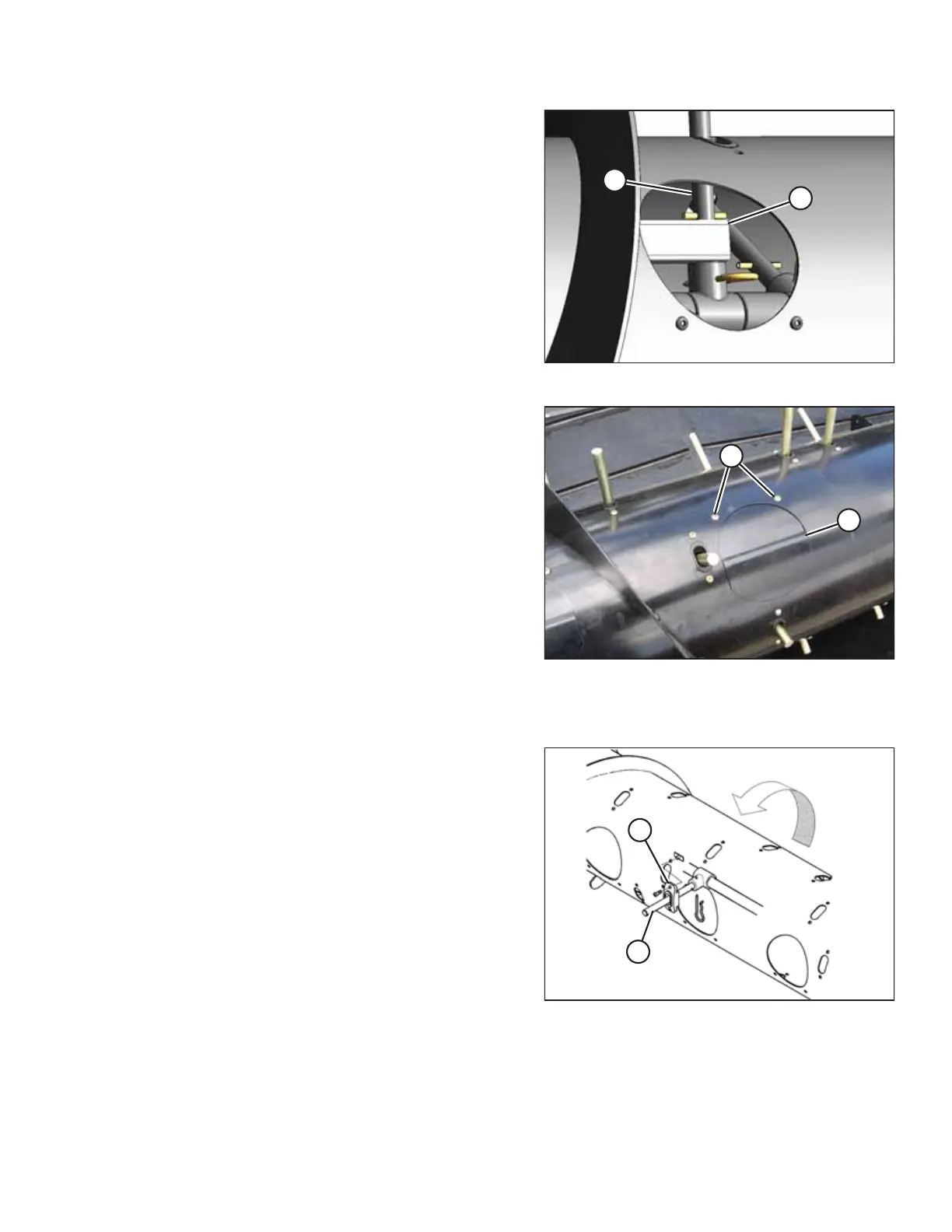
Figure 6.89: Tine
NOTE:
If installing the #6 tine (A), it must be inserted through
square drive tube (B).
7. Secure the #6 tine (A) in bushing (C) with hairpin (D). Install
the hairpin with the closed end leading with respect to
auger forward rotation.
Figure 6.90: Auger
8. Reinstall access cover (B) and secure with screws (A). Coat
screws with Loctite
®
#243 (or equivalent) and torque to
8.5 Nm (75 lbf∙in).
Replacing Feed Auger Tine Guides
Figure 6.91: Auger
1. Remove tine (B) and plastic guide (D). Refer to Removing
Feed Auger Tines, page 391.
MAINTENANCE AND SERVICING