214323 164 Revision B
Figure 4.71: Challenger
®
Combine Display
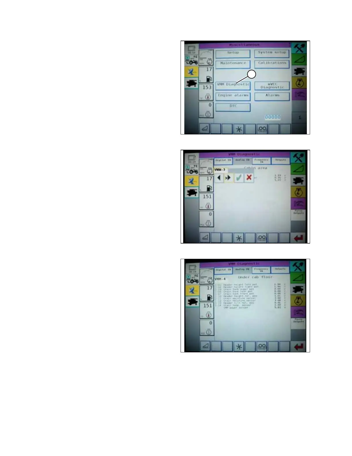
4. Go to the FIELD page on the combine monitor and select
the diagnostics icon. The MISCELLANEOUS page appears.
5. Select VMM DIAGNOSTIC button (A). The VMM
DIAGNOSTIC page appears.
Figure 4.72: Challenger
®
Combine Display
6. Go to the ANALOG IN tab and select VMM MODULE 3 by
pressing the text box below the four tabs. The voltage from
the AHHC sensors is now displayed on the page as HEADER
HEIGHT RIGHT POT and HEADER HEIGHT LEFT POT. Both
readings should be identical.
Figure 4.73: Challenger
®
Combine Display
7. Fully lower the combine feeder house (the adapter should
be fully separated from the header).
NOTE:
You may need to hold the HEADER DOWN switch for a few
seconds to ensure that the feeder house is fully lowered.
8. Record the height sensor voltage.
9. Raise the header so that the cutterbar is 150 mm (6 in.) off
of the ground.
10. Record the height sensor voltage.
11. Refer to Table 4.1, page 134 to compare the low and high height sensor voltages. If the height sensor voltages
recorded previously are not within the low and high limits, or if the range between the low and high limits is
insufficient, then adjust the voltage limits. Refer to 4.4.2 Adjusting Voltage Limits, page 137) for instructions.
AUTO HEADER HEIGHT CONTROL