Hardware
88
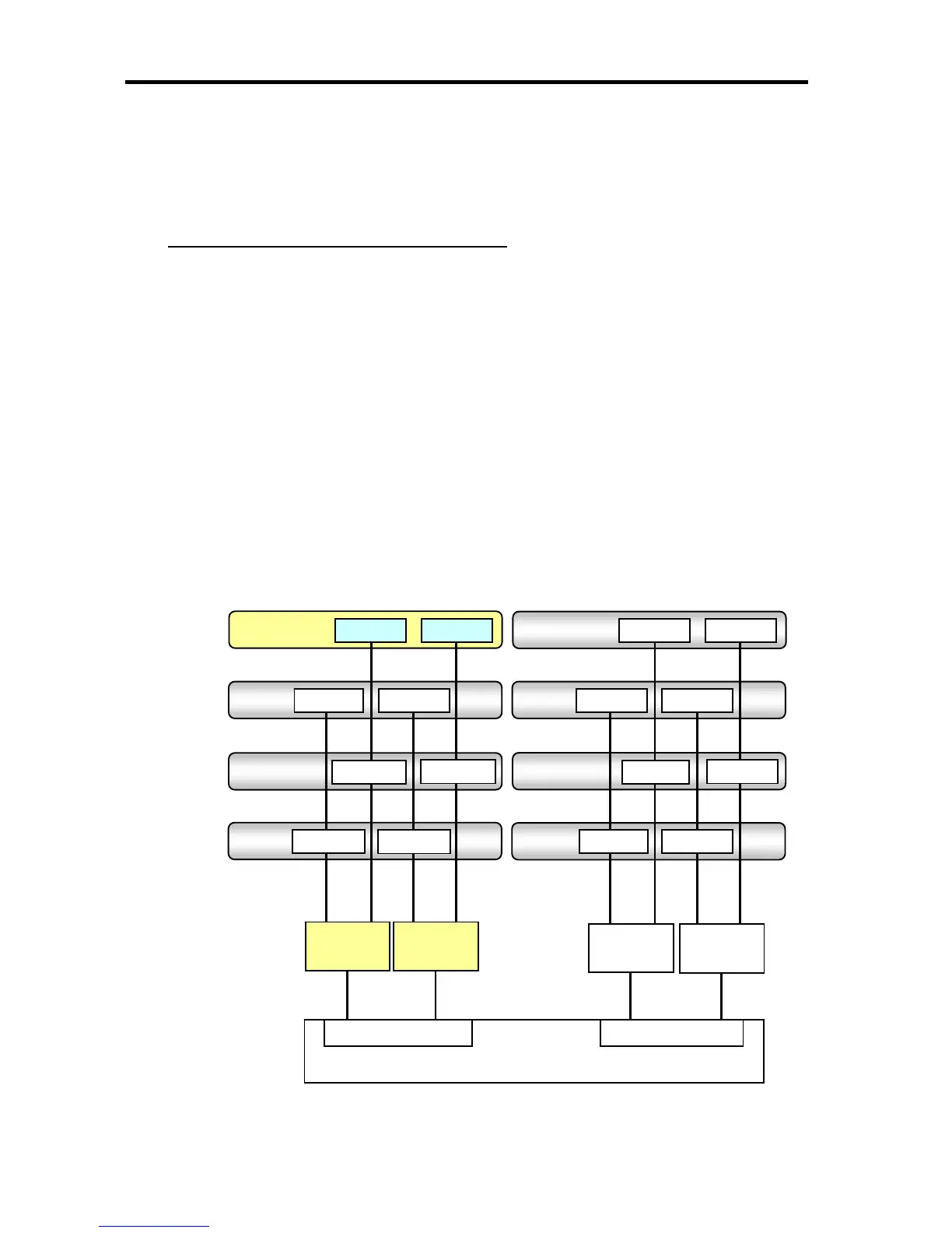
DIMM Mounting Rule
A1080a-S/A1080a-D/A1040a Model
A pair of DIMMs is defined as “PAIR” in this Guide, which is connected from the same channel
(Ch.x) number in two memory buffers connected to the same memory controller.
Example) DIMM #1 and DIMM #2 are regarded as PAIR #1, which are connected from
Ch.1 of the memory buffer #1 and Ch.1 of the memory buffer #2 in the following
memory configuration diagram.
The exact same type of DIMMs (Column/Row/Bank/Rank configuration) must be mounted on
the same PAIR.
In the A1080a-S/A1080a-D/A1040a model configuration, “PAIR” indicating pairs of DIMM is
the basic unit of DIMM control. DIMMs are added or reduced by using this PAIR unit.
Add in pairs starting from PAIR #1 in the order of lowest to highest number as a rule when
adding DIMMs.
Memory Configuration Diagram
PAIR #7
PAIR #8
PAIR #5 PAIR #6
DIMM #5
PAIR #3
DIMM #6
DIMM #7
PAIR #4
DIMM #8
DIMM #1
PAIR #1
DIMM #2
DIMM #3
PAIR #2
DIMM #4
DIMM #9
DIMM #14
DIMM #13
DIMM #10 DIMM #12
DIMM #11
DIMM #16 DIMM #15
Memory
Buffer#1
Memory
Buffer#2
Memory
Buffer#3
Memory
Buffer#4
Ch.0
Ch.0
Ch.1
Ch.1
Ch.0
Ch.0
Ch.1
Ch.1
Processor
Memory Controller#1
Memory Controller #2
Ch.
A
Ch.B
Ch.C
Ch.D