Connectors and Pin Assignments
309978-D Rev 01 F-5
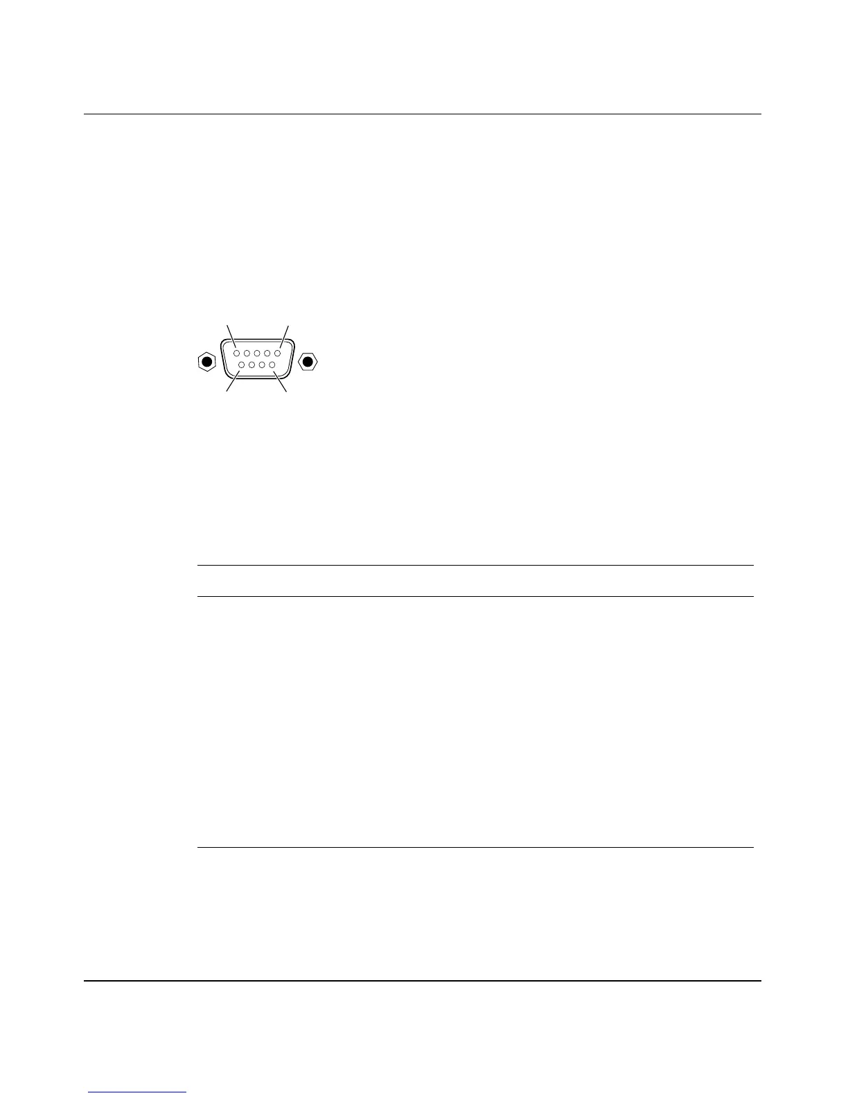
DB-9 (RS-232-D) Console/Comm Port Connector
The DB-9 Console/Comm Port connector (Figure F-4) is configured as a data
communications equipment (DCE) connector. The DSR and CTS signal outputs
are always asserted; the CD, DTR, RTS, and RI signal inputs are not used. This
configuration enables a management station (a PC or console terminal) to connect
directly to the switch using a straight-through cable.
Figure F-4. DB-9 Console/Comm Port Connector
Table F-2 lists the DB-9 Console/Comm Port connector pin assignments.
Table F-2. DB-9 Console/Comm Port Connector Pin Assignments
Pin Signal Description
1 CD Carrier detect (not used)
2 TXD Transmit data (output)
3 RXD Receive data (input)
4 DTR Data terminal ready (not used)
5 GND Signal ground
6 DSR Data set ready (output always asserted)
7 RTS Request to send (not used)
8 CTS Clear to send (output always asserted)
9 RI Ring indicator (not used)
Shell Chassis ground
5
6
9
1
619EA