BayStack 450 10/100/1000 Series Switches
309978-D Rev 01 1-41
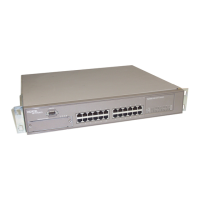
BayStack 400-ST1 Cascade Module
The front-panel components of the BayStack 400-ST1 Cascade Module are shown
in
Figure 1-17. Component descriptions follow the figure.
Figure 1-17. BayStack 400-ST1 Front-Panel Components
Cascade A Out Connector
Provides an attachment point for connecting this unit to another unit via the
cascade cable. A return cable from another unit’s Cascade A Out connector to this
unit’s Cascade A In connector completes the stack connection (see the example
shown in
Figure 1-18).
Unit Select Switch
The Unit Select switch (up = Base) determines the base unit for the stack
configuration (see
“Base Unit” on page 1-43). The Unit Select switch status is
displayed on the BayStack 450 LED display panel. When the Unit Select switch is
in the Base (up) position, all other Unit Select switches in the stack configuration
must be set to Off (down).
Cascade A Out
Cascade A In
Unit Select
Base
1 = Blank connectors (unused)
2 = Cascade A Out connector
3 = Unit Select switch
4 = Cascade A In connector
3
BS0031B
4
1
2