BayStack 450 10/100/1000 Series Switches
309978-D Rev 01 1-7
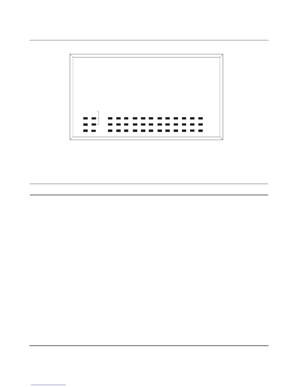
Figure 1-4. BayStack 450-12F LED Display Panel
Table 1-1. BayStack 450 Switch LED Descriptions
Label Type Color State Meaning
Pwr Power status Green On DC power is available to the switch’s internal circuitry.
Off No AC power to switch, or power supply failed.
Status System status Green On Self-test passed successfully and switch is operational.
Blinking A nonfatal error occurred during the self-test.
Off The switch failed the self-test.
RPSU RPSU status Green On The switch is connected to the HRPSU and can receive
power if needed.
Off The switch is not connected to the HRPSU or HRPSU is
not supplying power.
Cas Up Stack mode Off The switch is in standalone mode.
Green On The switch is connected to the upstream unit’s Cascade A
In connector.
Ye l l o w On The Cascade A Out connector (Cas Up) for this switch is
looped internally (wrapped to the secondary ring).
(continued)
BayStack 450-12F
BS45080A
450-12F Switch
BayStack
Status
Dwn
Pwr Up
153
Cas
RPSU Base
Activity
Link
F Dx
117926412810