RL78/G10 CHAPTER 5 CLOCK GENERATOR
R01UH0384EJ0311 Rev. 3.11 97
Dec 22, 2016
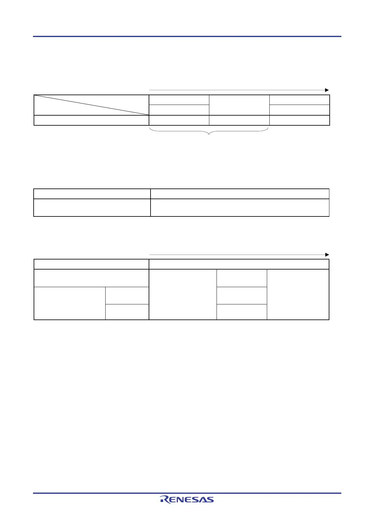
Table 5-3. CPU Clock Transition and SFR Register Setting Examples (2/2)
(2) CPU clock changing from high-speed system clock (B) to high-speed on-chip oscillator clock (A)
(Setting sequence of SFR registers)
Setting Flag of SFR Register
Status Transition
CSC Register
Oscillation accuracy
stabilization time
CKC Register
HIOSTOP MCM0
(B) → (A) 0 27 μs (typ.) 0
Unnecessary if the CPU is operating with the
high-speed on-chip oscillator clock
(3) • HALT mode (C) set while CPU is operating with high-speed on-chip oscillator clock (A)
• HALT mode (D) set while CPU is operating with high-speed system clock (B)
Status Transition Setting
(A) → (C)
(B) → (D)
Executing HALT instruction
(4) • STOP mode (E) set while CPU is operating with high-speed on-chip oscillator clock (A)
• STOP mode (F) set while CPU is operating with high-speed system clock (B)
(Setting sequence)
Status Transition Setting
(A) → (E)
Stopping peripheral
functions that cannot
operate in STOP mode
−
Executing STOP
instruction
(B) → (F) In X1 oscillation
Sets the OSTS
register
External clock
−
Remark (A) to (F) in Table 5-3 correspond to (A) to (F) in Figure 5-13.
 Loading...


