RL78/G10 CHAPTER 6 TIMER ARRAY UNIT
R01UH0384EJ0311 Rev. 3.11 127
Dec 22, 2016
6.3.6 Timer channel start register 0 (TS0, TSH0 (8-bit mode))
The TS0 and TSH0 registers are trigger registers that are used to initialize timer counter register 0n (TCR0n) and start
the counting operation of each channel.
When a bit of these registers is set to 1, the corresponding bit of timer channel enable status register 0 (TE0, TEH0) is
set to 1. The TSH0n and TS0n bits are immediately cleared to 0 when operation is enabled (TE0n = 1), because they are
trigger bits.
The TS0 and TSH0 registers can be set by a 1-bit or 8-bit memory manipulation instruction.
Reset signal generation clears TS0 and TSH0 registers to 00H.
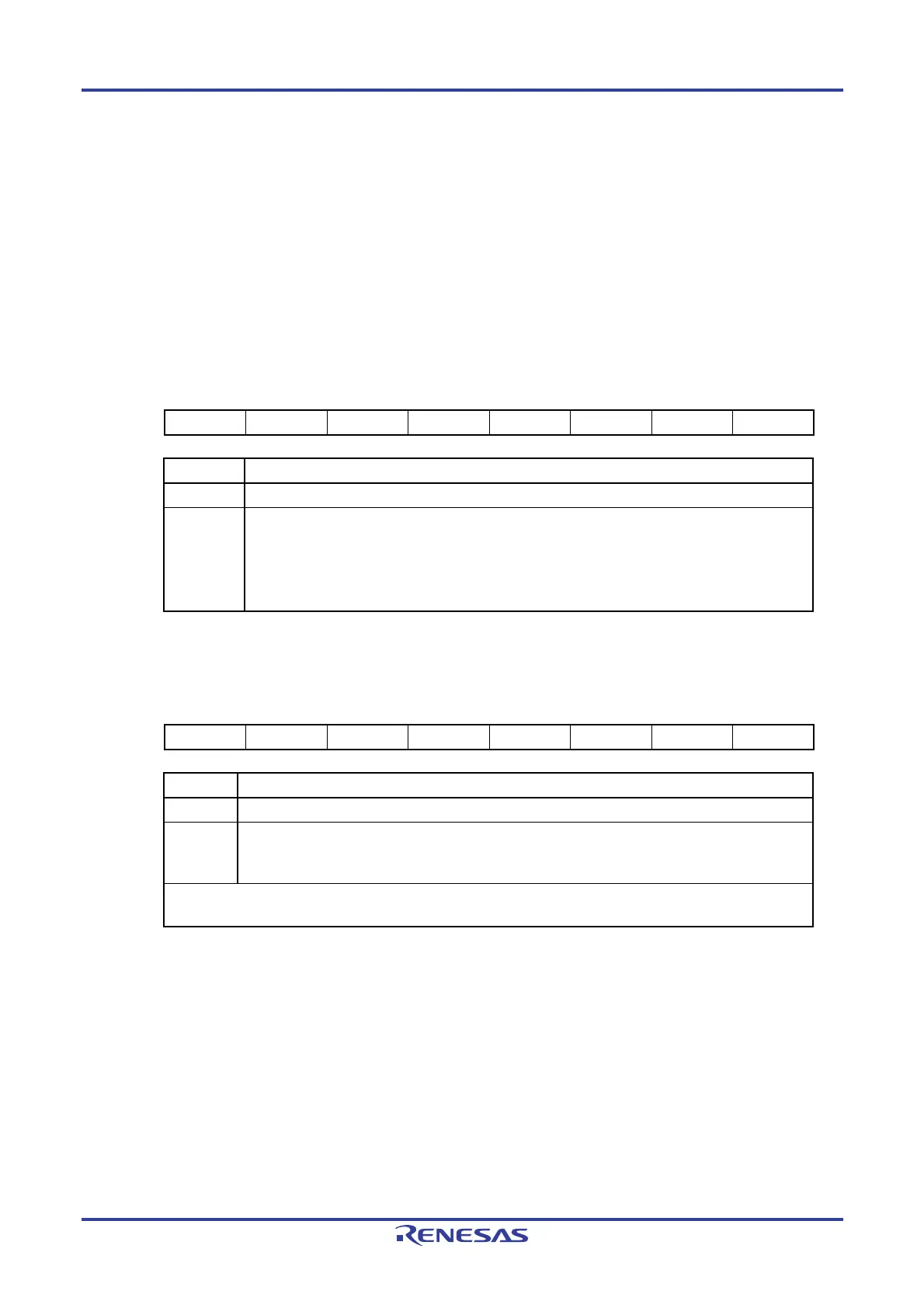
Figure 6-12. Format of Timer Channel Start Register 0 (TS0)
Address: F01B2H After reset: 00H R/W
Symbol 7 6 5 4 3 2 1 0
TS0 0 0 0 0 TS03
Note
TS02
Note
TS01 TS00
TS0n Operation enable (start) trigger of channel n (n = 0 to 3)
0 No trigger operation
1
The TE0n bit is set to 1 and the count operation becomes enabled.
The TCR0n register count operation start in the count operation enabled state varies depending on
each operation mode (see Table 6-5 in 6.5.2 Start timing of counter).
TS01 and TS03 bits are the trigger to enable operation (start operation) of the lower 8-bit timer when
channels 1 and 3 are in the 8-bit timer mode.
Figure 6-13. Format of Timer Channel Start Register 0 (TSH0)
Address: F01B3H After reset: 00H R/W
Symbol 7 6 5 4 3 2 1 0
TSH0 0 0 0 0 TSH03
Note
0 TSH01 0
TSH0n Operation enable (start) trigger of channel n (n = 1, 3)
0 No trigger operation
1
The TEH0n bit is set to 1 and the count operation becomes enabled.
The TCR0n register count operation start in the interval timer mode in the count operation enabled
state (see Table 6-5 in 6.5.2 Start timing of counter).
This bit is the trigger to enable operation (start operation) of the higher 8-bit timer when channels 1 and 3 are used
in the 8-bit timer mode.
Note 16-pin products only.
Cautions 1. Be sure to clear the following bits to 0.
TS0: Bits 2 to 7 in 10-pin products, bits 4 to 7 in 16-pin products
TSH0: Bits 0, 2 to 7 in 10-pin products, bits 0, 2, 4 to 7 in 16-pin products
2. When switching from a function that does not use TI0n pin input to one that does, the
following wait period is required from when timer mode register 0n (TMR0n) is set until
the TS0n bit is set to 1.
When the TI0n pin noise filter is enabled (TNFEN = 1):
Four cycles of the operation clock (f
MCK)
When the TI0n pin noise filter is disabled (TNFEN = 0):
Two cycles of the operation clock (f
MCK)
Remark When the TS0 and TSH0 registers are read, 0 is always read.

 Loading...


