RL78/G10 CHAPTER 5 CLOCK GENERATOR
R01UH0384EJ0311 Rev. 3.11 88
Dec 22, 2016
5.4 System Clock Oscillator
5.4.1 X1 oscillator (16-pin products only)
The X1 oscillator oscillates with a crystal resonator or ceramic resonator (1 to 20 MHz) connected to the X1 and X2
pins. An external clock can be input. In that case, input the clock signal to the EXCLK pin.
To use the X1 oscillator, set bits 7 and 6 (EXCLK, OSCSEL) of the clock operation mode control register (CMC) as
follows.
• Crystal or ceramic oscillation: EXCLK, OSCSEL = 0, 1
• External clock input: EXCLK, OSCSEL = 1, 1
When the X1 oscillator is not used, set the input port mode (EXCLK, OSCSEL = 0, 0).
When the pins are not used as input port pins, either, see Table 2-2 Connection of Unused Pins.
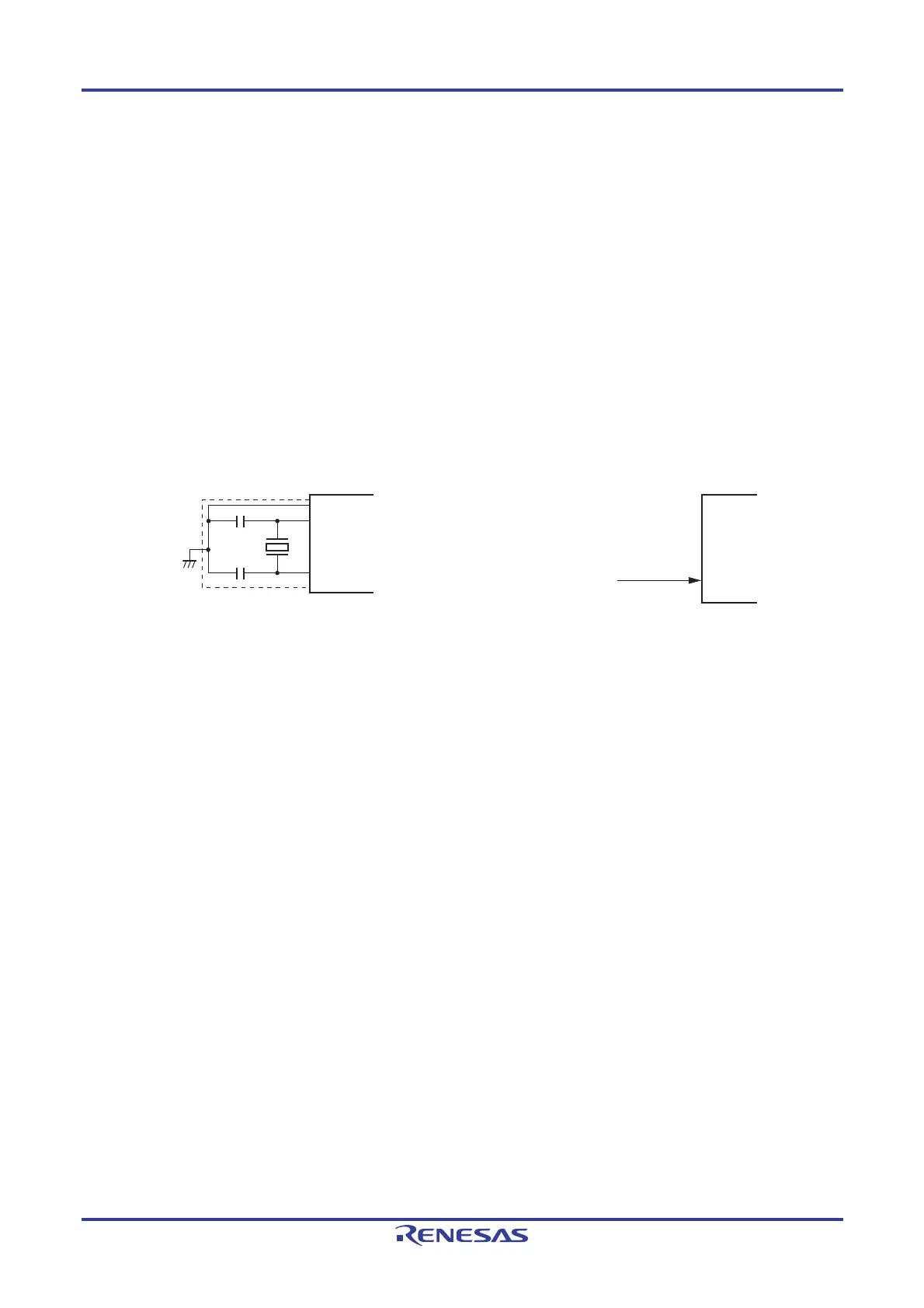
Figure 5-10 shows an example of the external circuit of the X1 oscillator.
Figure 5-10. Example of External Circuit of X1 Oscillator
(a) Crystal or ceramic oscillation (b) External clock input
V
SS
X1
X2
Crystal resonator
or
ceramic resonator
EXCLK
External clock
Caution When using the X1 oscillator, wire as follows in the area enclosed by the broken lines in the Figure 5-
10 to avoid an adverse effect from wiring capacitance.
• Keep the wiring length as short as possible.
• Do not cross the wiring with the other signal lines. Do not route the wiring near a signal line
through which a high fluctuating current flows.
• Always make the ground point of the oscillator capacitor the same potential as V
SS. Do not
ground the capacitor to a ground pattern through which a high current flows.
• Do not fetch signals from the oscillator.

 Loading...


