RL78/G10 CHAPTER 10 A/D CONVERTER
R01UH0384EJ0311 Rev. 3.11 249
Dec 22, 2016
10.3.3 A/D converter mode register 2 (ADM2)
This register is used to set the resolution of the A/D converter.
The ADM2 register can be set by a 1-bit or 8-bit memory manipulation instruction.
Reset signal generation clears this register to 00H.
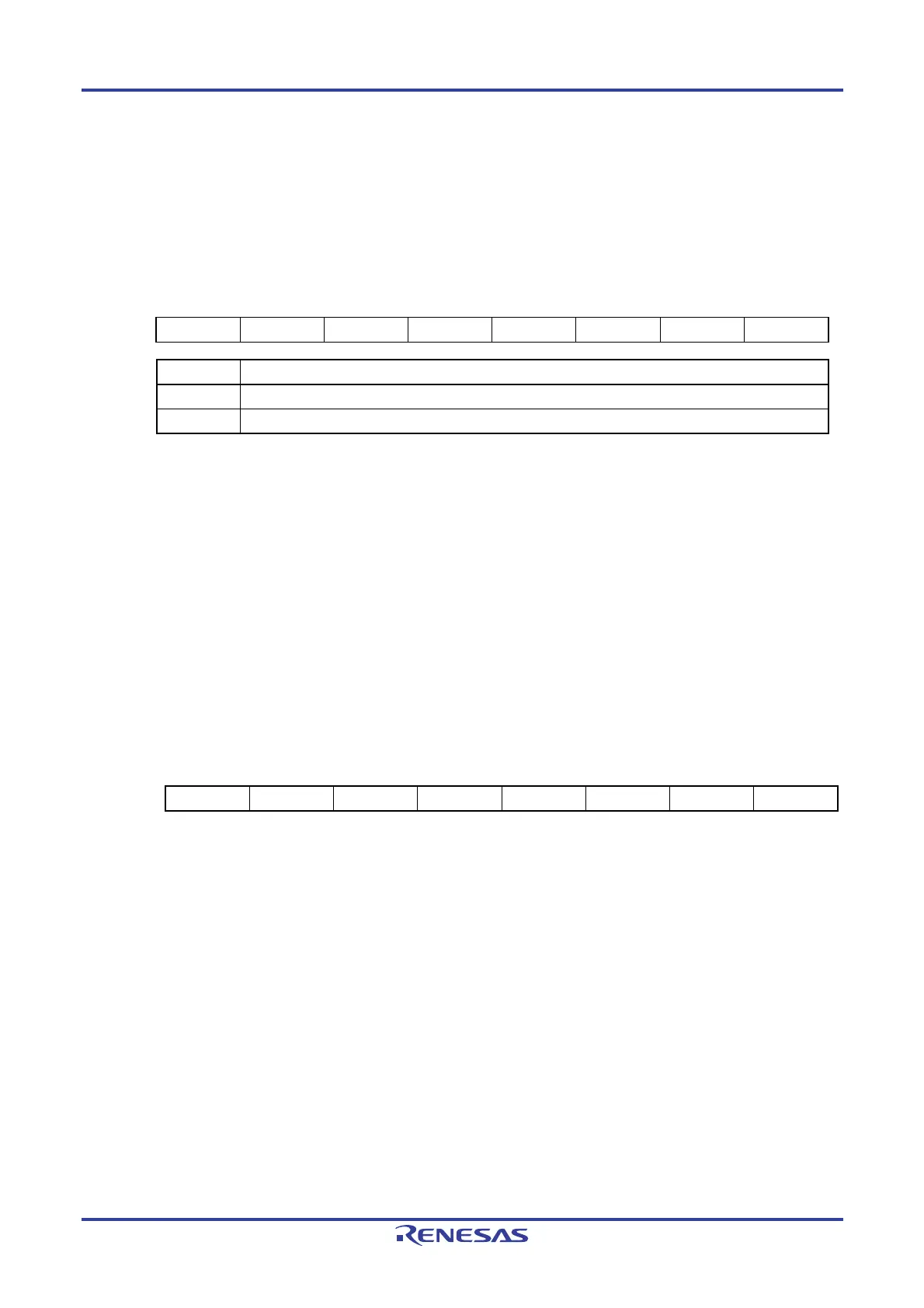
Figure 10-6. Format of A/D Converter Mode Register 2 (ADM2)
Address: F0010H After reset: 00H R/W
Symbol 7 6 5 4 3 2 1 <0>
ADM2 0 0 0 0 0 0 0 ADTYP
ADTYP Resolution of A/D conversion
0 10-bit resolution
1 8-bit resolution
Caution Rewrite the value of the ADM2 register in the conversion stopped status (while the ADCS
and ADCE bits are set to 0).
10.3.4 A/D conversion result higher-order bit storage register (ADCRH)
ADCRH is an 8-bit register which holds the result of A/D conversion. The conversion result is loaded from the
successive approximation register after A/D conversion ends. When 10-bit resolution is selected, the eight higher-order
bits of the A/D conversion result are stored in this register and the two lower-order bits of the A/D conversion result are
stored in ADCRL.
The ADCRH register can be read by an 8-bit memory manipulation instruction.
Reset signal generation clears this register to 00H.
Figure 10-7. Format of A/D Conversion Result Higher-Order Bit Storage Register (ADCRH)
Address: FFF1FH After reset: 00H R
Symbol 7 6 5 4 3 2 1 0
ADCRH ADCR9 ADCR8 ADCR7 ADCR6 ADCR5 ADCR4 ADCR3 ADCR2
Caution When writing to the A/D converter mode register 0 (ADM0) and the analog input channel
specification register (ADS), the contents of the ADCRH/ADCRL register may become
undefined. Read the conversion result following conversion completion before writing to the
ADM0 and ADS registers. Using timing other than the above may cause an incorrect
conversion result to be read.

 Loading...


