RL78/G10 CHAPTER 4 PORT FUNCTIONS
R01UH0384EJ0311 Rev. 3.11 60
Dec 22, 2016
4.3 Registers Controlling Port Function
Port functions are controlled by the following registers.
• Port mode registers 0, 4 (PM0, PM4)
• Port registers 0, 4, 12, 13 (P0, P4, P12, P13)
• Pull-up resistor option registers 0, 4, 12 (PU0, PU4, PU12)
• Port output mode register 0 (POM0)
• Port mode control register 0 (PMC0)
• Peripheral I/O redirection register (PIOR)
Caution Which registers and bits are included depends on the product. For registers and bits mounted on
each product, see Tables 4-2 and 4-3. Be sure to set bits that are not mounted to their initial values.
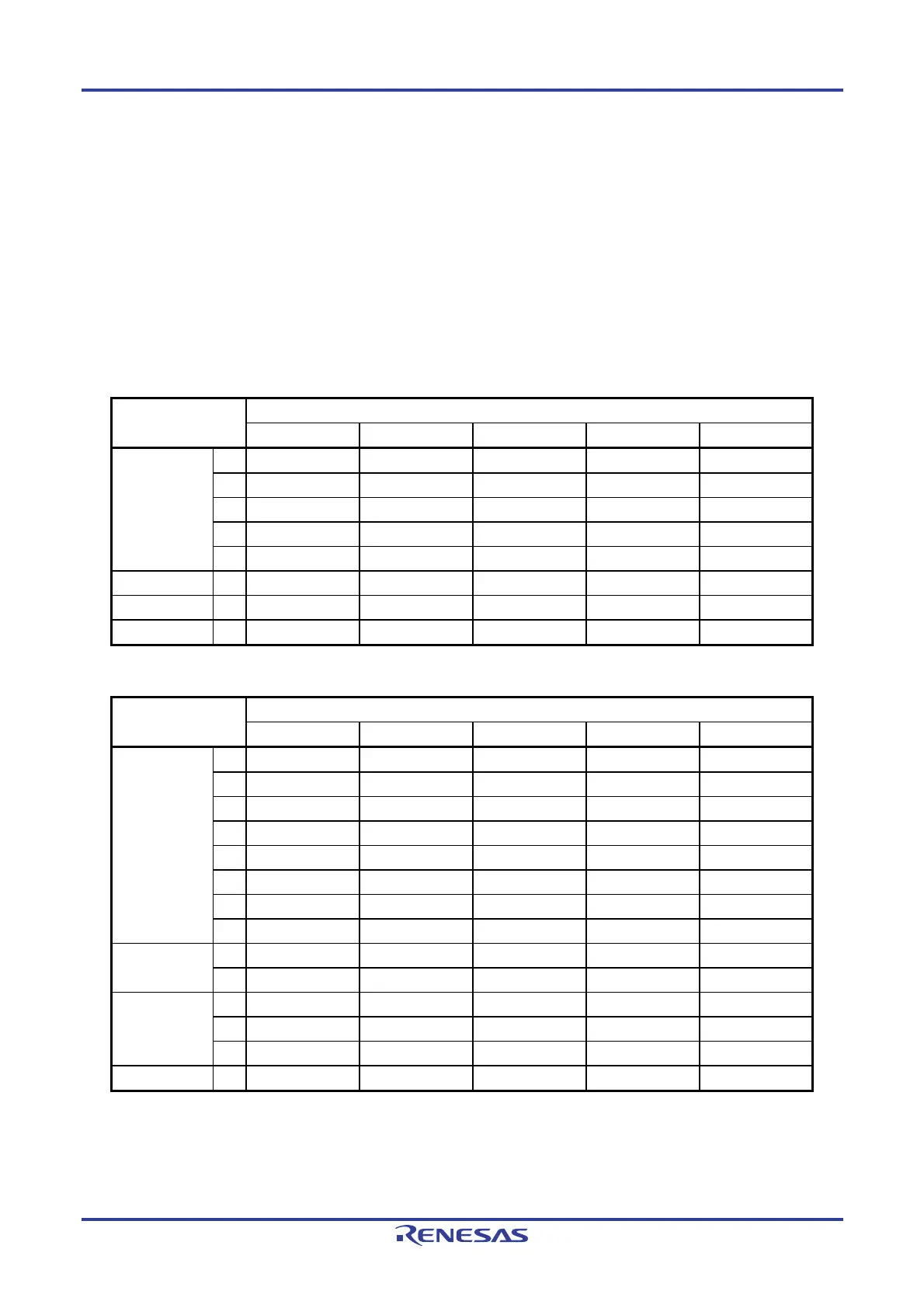
Table 4-2. Pm, PMn, PUy, POM0, PMC0 Registers and the Bits (10-pin Products)
Port
Bit name
Px register PMx register PUx register POMx register PMCx register
PORT0 0 P00 PM00 PU00 POM00
−
1 P01 PM01 PU01 POM01 PMC01
2 P02 PM02 PU02
−
PMC02
3 P03 PM03 PU03
−
PMC03
4 P04 PM04 PU04
−
PMC04
PORT4 0 P40 PM40 PU40
− −
PORT12 5 P125
−
PU125
− −
PORT13 7 P137
− − − −
Table 4-3. Pm, PMn, PUy, POM0, PMC0 Registers and the Bits (16-pin Products)
Port
Bit name
Px register PMx register PUx register POMx register PMCx register
PORT0 0 P00 PM00 PU00 POM00
−
1 P01 PM01 PU01 POM01 PMC01
2 P02 PM02 PU02
−
PMC02
3 P03 PM03 PU03
−
PMC03
4 P04 PM04 PU04
−
PMC04
5 P05 PM05 PU05
−
PMC05
6 P06 PM06 PU06 POM06 PMC06
7 P07 PM07 PU07 POM07 PMC07
PORT4 0 P40 PM40 PU40
− −
1 P41 PM41 PU41
− −
PORT12 1 P121
− − − −
2 P122
− − − −
5 P125
−
PU125
− −
PORT13 7 P137
− − − −
Remark m = 0, 4, 12, 13
n = 0, 4
y = 0, 4, 12
The format of each register is described below.

 Loading...


