RL78/G10 CHAPTER 6 TIMER ARRAY UNIT
R01UH0384EJ0311 Rev. 3.11 155
Dec 22, 2016
6.7 Timer Input (TI0n) Control
6.7.1 TI0n input circuit configuration
A signal is input from a timer input pin, goes through a noise filter and an edge detector, and is sent to a timer controller.
Enable the noise filter for the pin in need of noise removal. The following shows the configuration of the input circuit.
Figure 6-38. Input Circuit Configuration
CCS0n
Timer
controller
Count clock
selection
Trigger
selection
f
TCLK
f
MCK
Interrupt signal from master channel
TI0n pin
TNFEN0n STS0n2 to
STS0n0
CIS0n1,
CIS0n0
Edge
detection
Noise
filter
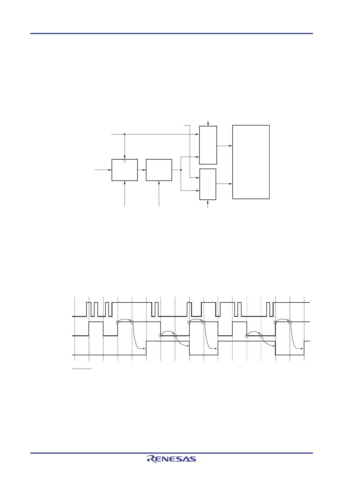
6.7.2 Noise filter
When the noise filter is disabled, the input signal is only synchronized with the operating clock (f
MCK) for channel n.
When the noise filter is enabled, after synchronization with the operating clock (f
MCK) for channel n, whether the signal
keeps the same value for two clock cycles is detected. The following shows differences in waveforms output from the
noise filter between when the noise filter for the TI0n pin is enabled and disabled.
Figure 6-39. Sampling Waveforms through TI0n Input Pin with Noise Filter Enabled and Disabled
TI0n pin
Operating clock (f
MCK
)
Noise filter disabled
Noise filter enabled

 Loading...


