RL78/G10 CHAPTER 14 INTERRUPT FUNCTIONS
R01UH0384EJ0311 Rev. 3.11 504
Dec 22, 2016
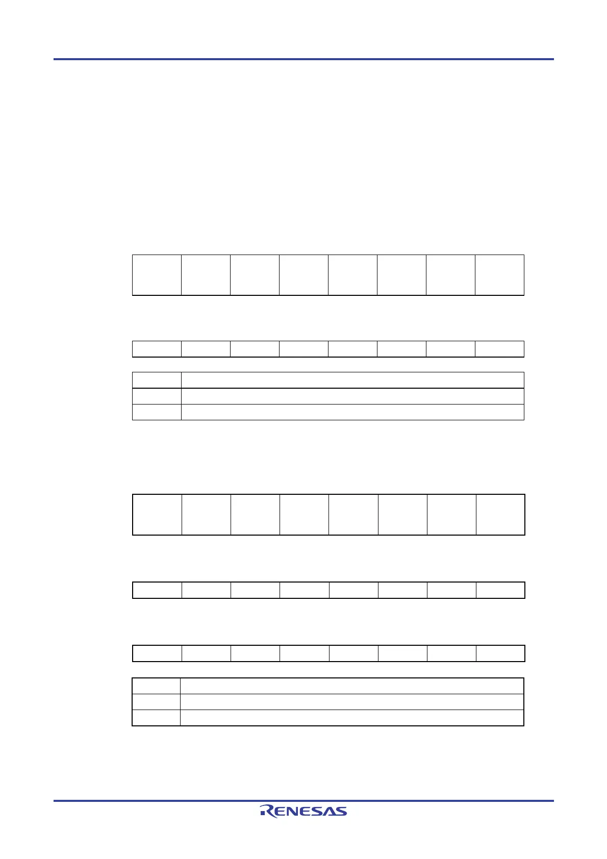
14.3.2 Interrupt mask flag registers (MK0L, MK0H, MK1L)
The interrupt mask flags are used to enable/disable the corresponding maskable interrupt servicing.
The MK0L, MK0H, and MK1L registers can be set by a 1-bit or 8-bit memory manipulation instruction. Reset signal
generation sets these registers to FFH.
Remark If an instruction that writes data to this register is executed, the number of instruction execution clocks
increases by 2 clocks.
Figure 14-4. Format of Interrupt Mask Flag Registers (MK0L, MK0H) (10-pin product)
ddress: FFFE4H After reset: FFH R/W
Symbol <7> <6> <5> <4> <3> <2> <1> <0>
MK0L TMMK00 TMMK01H SREMK0 SRMK0
STMK0
CSIMK00
IICMK00
PMK1 PMK0 WDTIMK
ddress: FFFE5H After reset: FFH R/W
Symbol 7 6 5 4 3 <2> <1> <0>
MK0H 1 1 1 1 1 KRMK ADMK TMMK01
XXMKXX Interrupt servicing control
0 Interrupt servicing enabled
1 Interrupt servicing disabled
Figure 14-5. Format of Interrupt Mask Flag Registers (MK0L, MK0H, MK1L) (16-pin product)
Address: FFFE4H After reset: FFH R/W
Symbol <7> <6> <5> <4> <3> <2> <1> <0>
MK0L TMMK00 TMMK01H SREMK0
SRMK0
CSIMK01
STMK0
CSIMK00
IICMK00
PMK1 PMK0 WDTIMK
Address: FFFE5H After reset: FFH R/W
Symbol <7> <6> <5> <4> <3> <2> <1> <0>
MK0H TMMK02 IICAMK0 TMMK03H PMK3 PMK2 KRMK ADMK TMMK01
Address: FFFE6H After reset: FFH R/W
Symbol 7 6 5 4 3 <2> <1> <0>
MK1L 1 1 1 1 1 CMPMK0 ITMK TMMK03
XXMKXX Interrupt servicing control
0 Interrupt servicing enabled
1 Interrupt servicing disabled
Caution Do not change undefined bit data.

 Loading...


