RL78/G10 CHAPTER 12 SERIAL ARRAY UNIT
R01UH0384EJ0311 Rev. 3.11 303
Dec 22, 2016
12.4 Operation Stop Mode
Each serial interface of serial array unit has the operation stop mode.
In this mode, serial communication cannot be executed, thus reducing the power consumption.
In addition, the serial interface function alternate pins can be used as port function pins in this mode.
12.4.1 Stopping the operation by units
The stopping of the operation by units is set by using peripheral enable register 0 (PER0).
The PER0 register is used to enable or disable supplying the clock to the peripheral hardware. Clock supply to a
hardware macro that is not used is stopped in order to reduce the power consumption and noise.
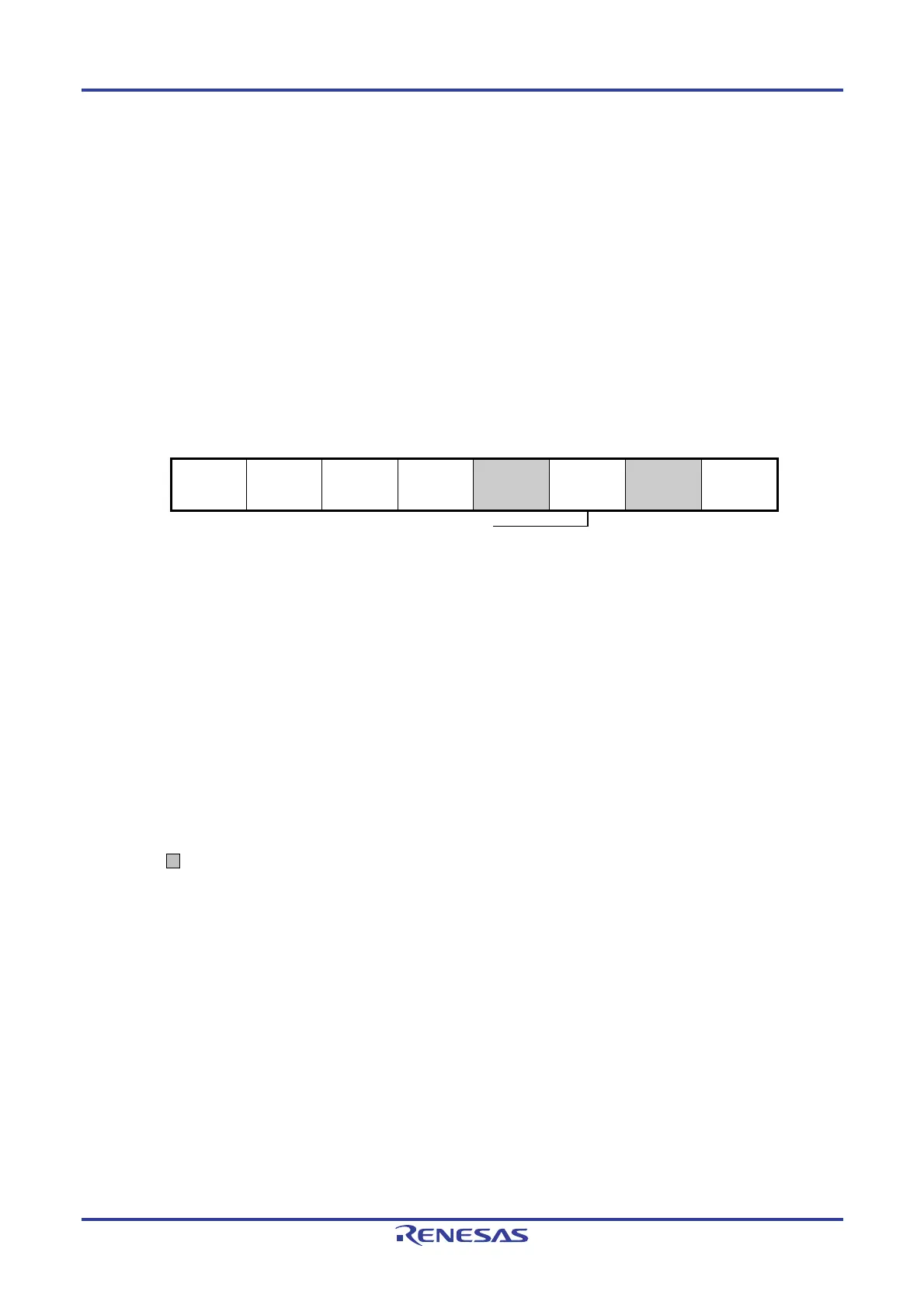
Figure 12-20. Peripheral Enable Register 0 (PER0) Setting When Stopping Operation by Units
Note 16-pin products only.
Cautions 1. When setting serial array unit 0, be sure to first set the control registers of the serial array unit 0
with the SAU0EN bit set to 1. If SAU0EN = 0, control registers of serial array unit 0 become default
values and writing to them is ignored (except for the noise filter enable register 0 (NFEN0), input
switch control register (ISC), port output mode register 0 (POM0), port mode register 0 (PM0), port
mode control register 0 (PMC0), and port register 0 (P0)).
2. Be sure to clear the following bits to 0.
10-pin products: Bits 1, 3, 4, 6, and 7
16-pin products: Bits 1 and 3
Remark : Setting disabled (fixed by hardware)
×: Bits not used with serial array units (depending on the settings of other peripheral functions)
0/1: Set to 0 or 1 depending on the usage of the user.
(a) Peripheral enable register 0 (PER0) … Set only the bit of SAU0 to be stopped to 0.
<7> <6> <5> <4> 3 <2> 1 <0>
PER0
TMKAEN
Note
×
CMPEN
Note
×
ADCEN
×
IICA0EN
Note
×
0
SAU0EN
0/1
0
TAU0EN
×
Control of SAU0 input clock
0: Stops supply of input clock
1: Su
lies in
ut clock

 Loading...


