RL78/G10 CHAPTER 3 CPU ARCHITECTURE
R01UH0384EJ0311 Rev. 3.11 27
Dec 22, 2016
3.1.1 Internal program memory space
The internal program memory space stores the program and table data.
The RL78/G10 products incorporate internal ROM (flash memory), as shown below.
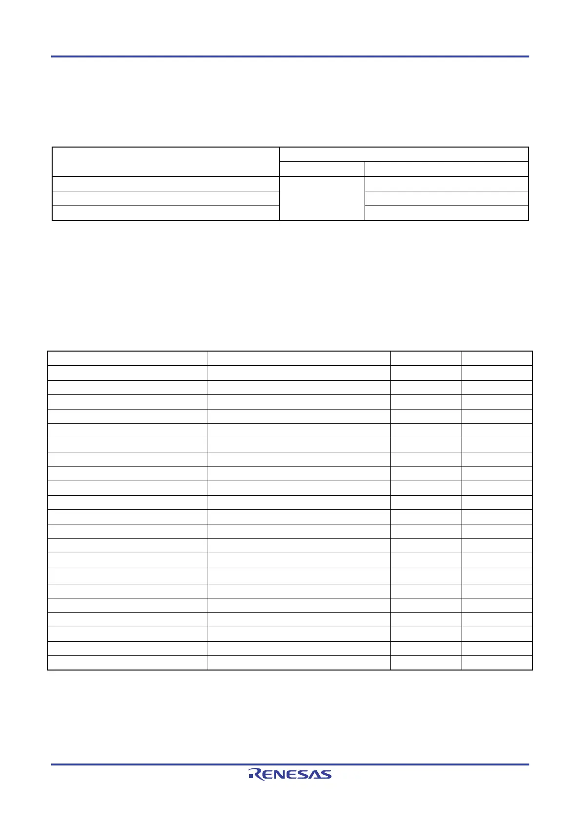
Table 3-1. Internal ROM Capacity
Part Number Internal ROM
Structure Capacity
R5F10Y14, R5F10Y44 Flash memory 1024 × 8 bits (00000H to 003FFH)
R5F10Y16, R5F10Y46 2048 × 8 bits (00000H to 007FFH)
R5F10Y17, R5F10Y47 4048 × 8 bits (00000H to 00FFFH)
The internal program address space is divided into the following areas.
(1) Vector table area
The 128-byte area of 00000H to 0007FH is reserved as a vector table area. The program start addresses for branch
upon reset or generation of each interrupt request are stored in the vector table area. Furthermore, the interrupt jump
addresses are assigned to a 64 KB address area of 00000H to 0FFFFH, because the vector code is 2 bytes.
Of 16-bit addresses, the lower 8 bits are stored at even addresses and the higher 8 bits are stored at odd addresses.
Table 3-2. Vector Table
Vector Table Address Interrupt Source 16-pin 10-pin
00000H RESET, SPOR, WDT, TRAP √ √
00004H INTWDTI √ √
00006H INTP0 √ √
00008H INTP1 √ √
0000AH INTST0, INTCSI00, INTIIC00 √ √
0000CH INTSR0, INTCSI01 √ Note
0000EH INTSRE0 √ √
00010H INTTM01H √ √
00012H INTTM00 √ √
00014H INTTM01 √ √
00016H INTAD √ √
00018H INTKR √ √
0001AH INTP2 √
⎯
0001CH INTP3 √
⎯
0001EH INTTM03H
√
⎯
00020H INTIICA0 √
⎯
00022H INTTM02 √
⎯
00024H INTTM03 √
⎯
00026H INTIT √
⎯
00028H INTCMP0 √
⎯
0007EH BRK √ √
Note INTSR0 only.

 Loading...


