RL78/G10 CHAPTER 8 CLOCK OUTPUT/BUZZER OUTPUT CONTROLLER
R01UH0384EJ0311 Rev. 3.11 231
Dec 22, 2016
8.2 Configuration of Clock Output/Buzzer Output Controller
The clock output/buzzer output controller includes the following hardware.
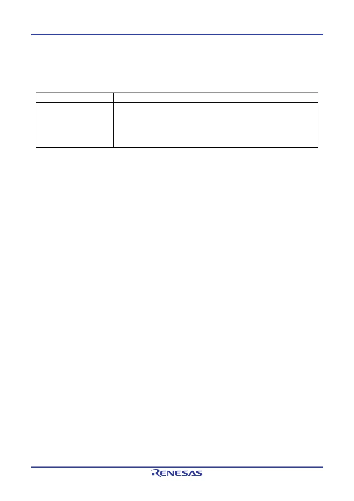
Table 8-1. Configuration of Clock Output/Buzzer Output Controller
Item Configuration
Control registers Clock output select register 0 (CKS0)
Port mode register 0 (PM0) [Port mode register 4 (PM4)]
Port register 0 (P0) [Port register 4 (P4)]
Port mode control register 0 (PMC0)
Peripheral I/O redirection register (PIOR)
Remark Functions in brackets in the above table can be assigned via settings in the peripheral I/O redirection register
(PIOR).
8.3 Registers Controlling Clock Output/Buzzer Output Controller
The following registers are used to control the clock output/buzzer output controller.
• Clock output select register 0 (CKS0)
• Port mode register 0 (PM0) [Port mode register 4 (PM4)]
• Port mode control register 0 (PMC0)
• Peripheral I/O redirection register (PIOR)
Remark Functions in brackets can be assigned via settings in the peripheral I/O redirection register (PIOR).

 Loading...


