RL78/G10 CHAPTER 15 KEY INTERRUPT FUNCTION
R01UH0384EJ0311 Rev. 3.11 521
Dec 22, 2016
15.4 Key Interrupt Operation
15.4.1 When not using the key interrupt flag (KRMD = 0)
A key interrupt (INTKR) is generated when the valid edge specified by the setting of the KREG bit is input to a key
interrupt pin (KR0 to KR5). The channel to which the valid edge was input can be identified by reading the port register
and checking the port level after the key interrupt (INTKR) is generated.
The INTKR signal changes according to the input level of the key interrupt input pin (KR0 to KR5).
Figure 15-5. Operation of INTKR Signal When a Key Interrupt is Input to a Single Channel
(When KRMD = 0 and KREG = 0)
KR0
INTKR
Delay
time
Delay
time
Note
KRIF
Note Acknowledgment of vectored interrupt request or bit cleared by software
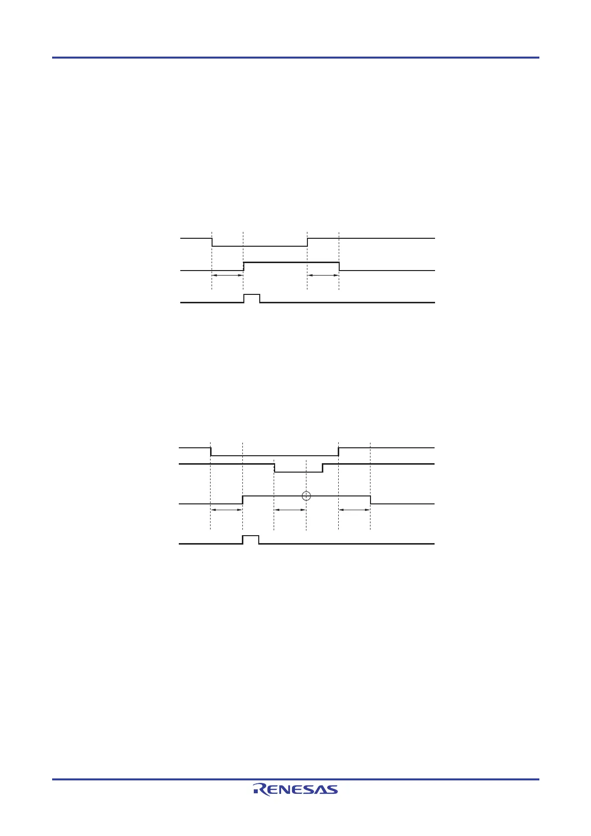
The operation when a valid edge is input to multiple key interrupt input pins is shown in Figure 15-6 below. The INTKR
signal is set while a low level is being input to one pin (when KREG is set to 0). Therefore, even if a falling edge is input to
another pin in this period, a key interrupt (INTKR) will not be generated again (<1> in the figure).
Figure 15-6. Operation of INTKR Signal When Key Interrupts Are Input to Multiple Channels
(When KRMD = 0 and KREG = 0)
KR0
KR1
<1>
INTKR
KRIF
Delay
time
Note
Delay
time
Delay
time
Note Acknowledgment of vectored interrupt request or bit cleared by software

 Loading...


