RL78/G10 CHAPTER 17 RESET FUNCTION
R01UH0384EJ0311 Rev. 3.11 537
Dec 22, 2016
17.2 States of Operation During Reset Periods
Table 17-1 shows the states of operation during reset periods. Table 17-2 shows the state of the hardware after
acceptance of a reset.
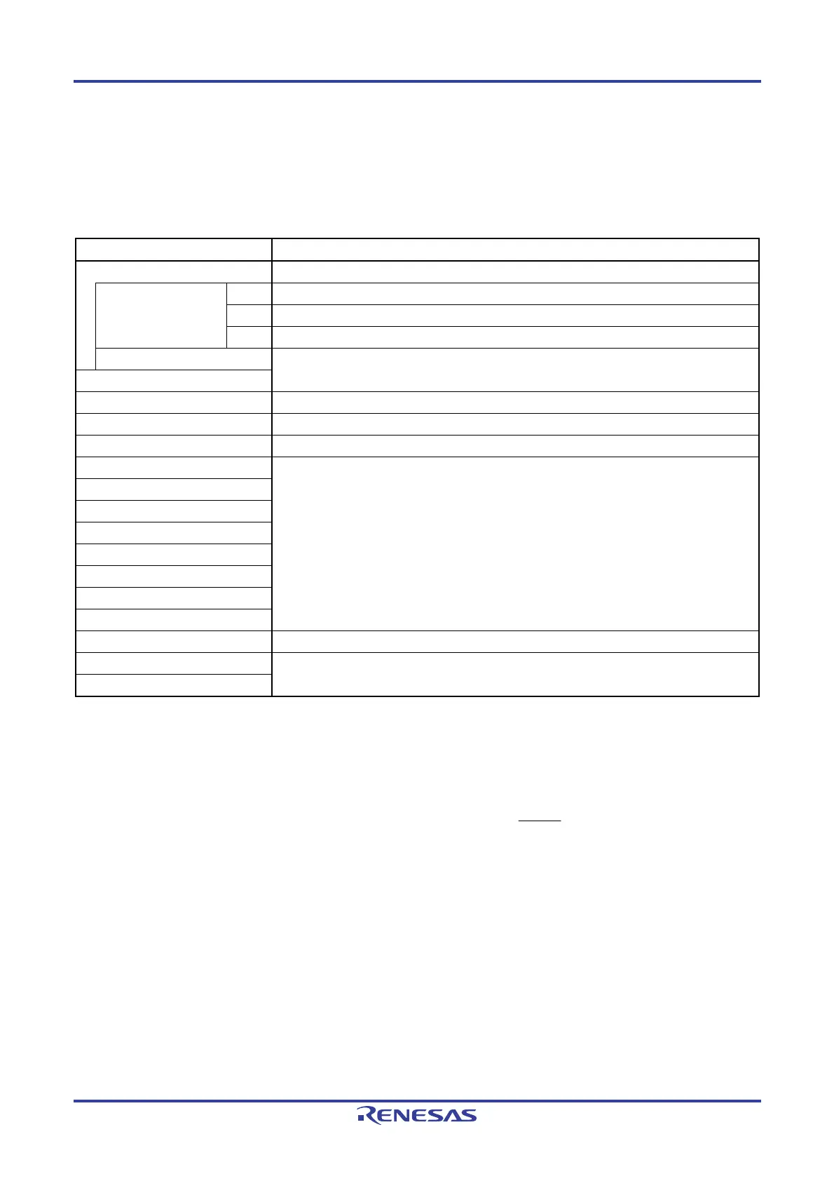
Table 17-1. States of Operation During Reset Period
Item During Reset Period
System clock Clock supply to the CPU is stopped.
Main system clock fIH Operation stopped
fX Operation stopped (the X1 and X2 pins are input port mode)
fEX Clock input invalid (the pin is input port mode)
fIL Operation stopped
CPU
Code flash memory Operation stopped
RAM Operation stopped
Port (latch) High impedance
Note 2
Timer array unit Operation stopped
12-bit Interval timer
Watchdog timer
Clock output/buzzer output
A/D converter
Comparator
Note 1
Serial array unit (SAU)
Serial interface (IICA)
Selectable power-on-reset function Detection operation possible
External interrupt Operation stopped
Key interrupt function
Notes 1. 16-pin products only.
2. Statuses of P40 and P125 pins are as follows
• P40: High-impedance during external reset period or reset period by the data retention power supply
voltage. High level during other types of reset period or after receiving a reset (connected to the
internal pull-up resistor).
• P125: Low level during external reset period (low level input to RESET pin). High level during other types
of reset period or after receiving a reset (connected to the internal pull-up resistor).
Remark f
IH: High-speed on-chip oscillator clock
f
X: X1 clock
f
EX: External main system clock
fIL: Low-speed on-chip oscillator clock

 Loading...


