RL78/G10 CHAPTER 17 RESET FUNCTION
R01UH0384EJ0311 Rev. 3.11 536
Dec 22, 2016
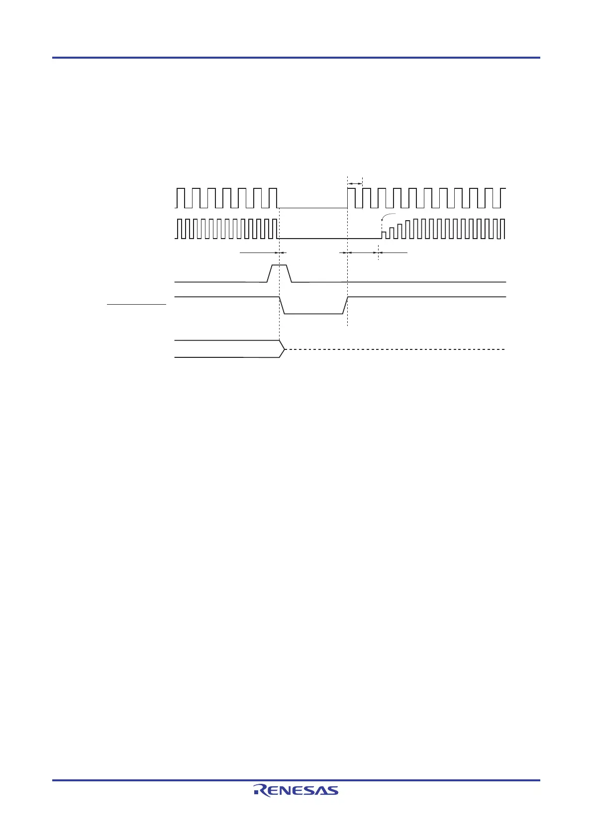
Release from the reset state is automatic in the cases of a reset due to the watchdog timer overflow or execution of
illegal instruction. After reset processing, execution of the program with the high-speed on-chip oscillator clock as the
operating clock starts.
Figure 17-3. Timing of Reset Due to Watchdog Timer Overflow or Execution of Illegal Instruction
Normal operation
Reset period
(oscillation stop)
CPU status
Execution of Illegal
Instruction/
Watchdog timer
overflow
Internal reset signal
Hi-Z
Note 2
High-speed system clock
(when X1 oscillation is selected)
Note 1
High-speed on-chip
oscillator clock
Starting X1 oscillation is specified by software.
Normal operation
(high-speed on-chip oscillator clock)
Wait for oscillation
accuracy stabilization
Reset processing
Port pin
50
µ
s
(typ.)
Notes 1. 16-pin products only.
2. Statuses of port pins P40 and P125 pins are as follows.
• High level during reset period or after receiving a reset (connected to the internal pull-up resistor).
Remark For the reset timing due to the voltage detection by the selectable power-on-reset (SPOR) circuit, see
CHAPTER 18 SELECTABLE POWER-ON-RESET CIRCUIT.

 Loading...


