RL78/G10 CHAPTER 5 CLOCK GENERATOR
R01UH0384EJ0311 Rev. 3.11 84
Dec 22, 2016
5.3.5 Oscillation stabilization time select register (OSTS)
This register is used to select the X1 clock oscillation stabilization wait time when the STOP mode is released.
When the X1 clock is selected as the CPU clock, the operation automatically waits for the time set using the OSTS
register after the STOP mode is released.
The oscillation stabilization time can be checked up to the time set using the OSTC register.
The OSTS register can be set by an 8-bit memory manipulation instruction.
Reset signal generation sets the OSTS register to 07H.
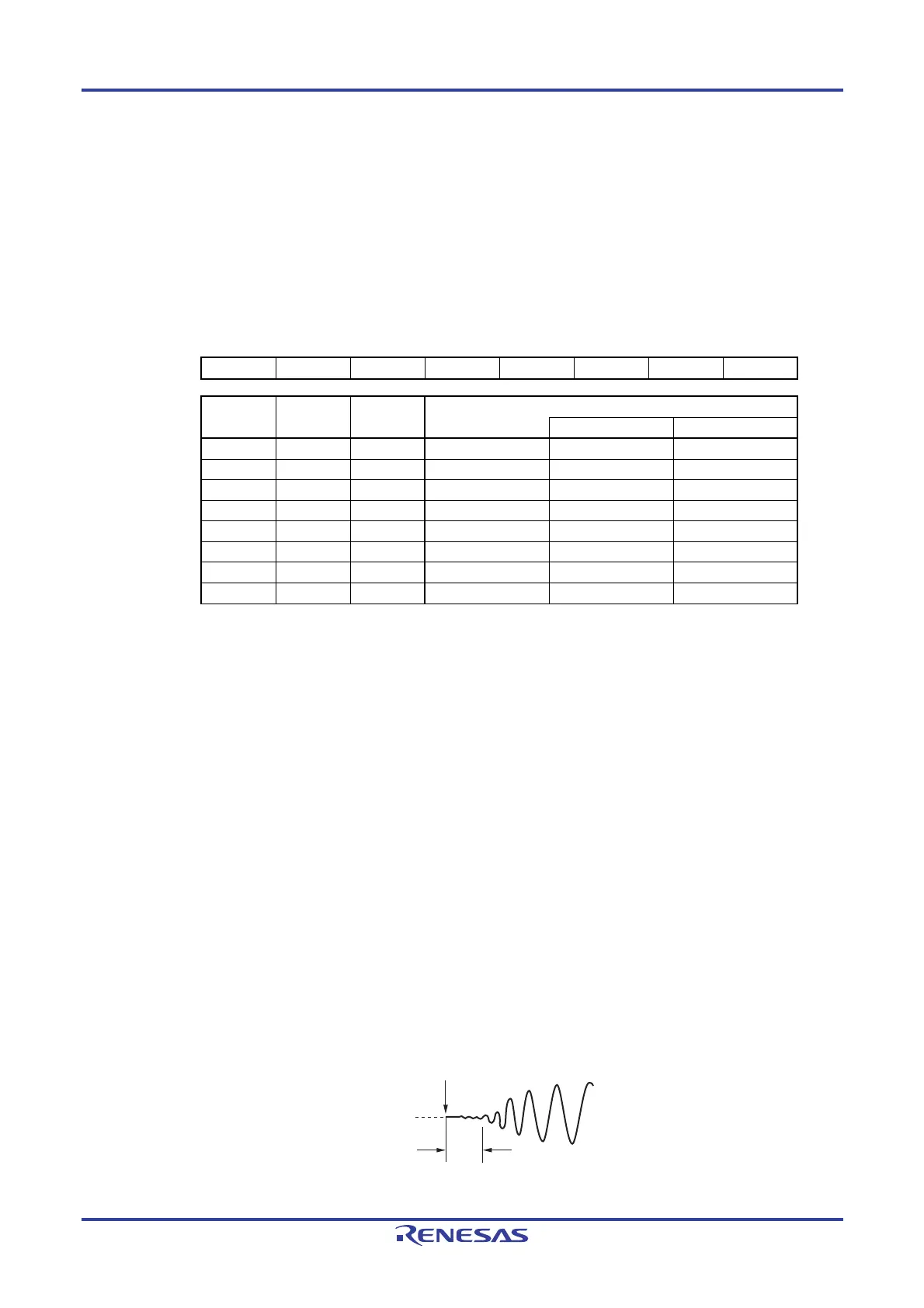
Figure 5-6. Format of Oscillation Stabilization Time Select Register (OSTS)
Address: FFFA3H After reset: 07H R/W
Symbol 7 6 5 4 3 2 1 0
OSTS 0 0 0 0 0 OSTS2 OSTS1 OSTS0
OSTS2 OSTS1 OSTS0 Oscillation stabilization time selection
fX = 10 MHz fX = 20 MHz
0 0 0 (2
8
+16)/fX 27.2
μ
s 13.6
μ
s
0 0 1 (2
9
+16)/fX 52.8
μ
s 26.4
μ
s
0 1 0 (2
10
+16)/fX 104
μ
s 52.0
μ
s
0 1 1 (2
11
+16)/fX 206
μ
s 103
μ
s
1 0 0 (2
13
+16)/fX 820
μ
s 410
μ
s
1 0 1 (2
15
+16)/fX 3.27 ms 1.63 ms
1 1 0 (2
17
+16)/fX 13.1 ms 6.55 ms
1 1 1 (2
18
+16)/fX 26.2 ms 13.1 ms
Cautions 1. To set the STOP mode when the X1 clock is used as the CPU clock, set the
OSTS register before executing the STOP instruction.
2. Change the setting of the OSTS register before setting the MSTOP bit of the
clock operation status control register (CSC) to 0.
3. Do not change the value of the OSTS register during the X1 clock oscillation
stabilization time.
4. The oscillation stabilization time counter counts up to the oscillation
stabilization time set by the OSTS register.
In the following cases, set the oscillation stabilization time of the OSTS register
to the value greater than the count value which is to be checked by the OSTC
register after the oscillation starts.
• If the X1 clock starts oscillation while the high-speed on-chip oscillator
clock is being used as the CPU clock.
• If the STOP mode is entered and then released while the high-speed on-
chip oscillator clock is being used as the CPU clock with the X1 clock
oscillating. (Note, therefore, that only the status up to the oscillation
stabilization time set by the OSTS register is set to the OSTC register after
the STOP mode is released.)
5. The X1 clock oscillation stabilization wait time does not include the time until
clock oscillation starts (“a” below).
a
STOP mode release
X1 pin voltage
waveform
Remark f
X: X1 clock oscillation frequency

 Loading...


