RL78/G10 CHAPTER 6 TIMER ARRAY UNIT
R01UH0384EJ0311 Rev. 3.11 118
Dec 22, 2016
6.3.1 Peripheral enable register 0 (PER0)
This registers is used to enable or disable supplying the clock to the peripheral hardware. Clock supply to a hardware
macro that is not used is stopped in order to reduce the power consumption and noise.
When the timer array unit is used, be sure to set bit 0 (TAU0EN) of this register to 1.
The PER0 register can be set by a 1-bit or 8-bit memory manipulation instruction.
Reset signal generation clears this register to 00H.
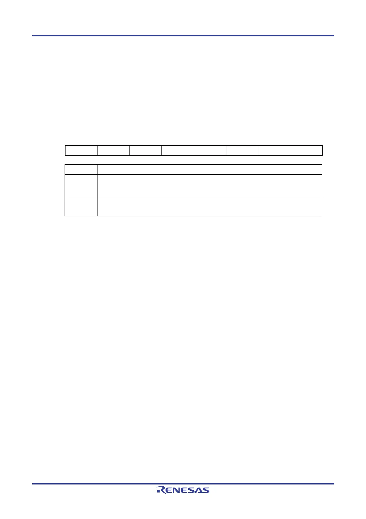
Figure 6-6. Format of Peripheral Enable Register 0 (PER0)
Address: F00F0H After reset: 00H R/W
Symbol <7> <6> <5> <4> 3 <2> 1 <0>
PER0 TMKAEN
Note
CMPEN
Note
ADCEN IICA0EN
Note
0 SAU0EN 0 TAU0EN
TAU0EN Control of timer array unit input clock
0
Stops supply of input clock.
• SFR used by the timer array unit cannot be written.
• The timer array unit is in the reset status.
1
Supplies input clock.
• SFR used by the timer array unit can be read/written.
Note 16-pin products only.
Cautions 1. When setting the timer array unit, be sure to set the following registers first while the
TAU0EN bit is set to 1. If TAU0EN = 0, the values of the registers which control the timer
array unit are cleared to their initial values and writing to them is ignored (except for the
noise filter enable register 1 (NFEN1), input switch control register (ISC), port mode
registers 0, 4 (PM0, PM4), port registers 0, 4 (P0, P4), and port mode control register 0
(PMC0)).
• Timer counter register 0n (TCR0nH, TCR0nL)
• Timer data register 0n (TDR0nH, TDR0nL)
• Timer clock select register 0 (TPS0)
• Timer channel enable status register 0 (TE0, TEH0)
• Timer channel start register 0 (TS0, TSH0)
• Timer channel stop register 0 (TT0, TTH0)
• Timer output enable register 0 (TOE0)
• Timer output register 0 (TO0)
• Timer output level register 0 (TOL0)
• Timer output mode register 0 (TOM0)
• Timer mode register 0n (TMR0nH, TMR0nL)
• Timer status register 0n (TSR0n)
2. Be sure to clear the following bits to 0.
10-pin products: bits 1, 3, 4, 6, 7
16-pin products: bits 1, 3

 Loading...


