RL78/G10 CHAPTER 15 KEY INTERRUPT FUNCTION
R01UH0384EJ0311 Rev. 3.11 522
Dec 22, 2016
15.4.2 When using the key interrupt flag (KRMD = 1)
A key interrupt (INTKR) is generated when the valid edge specified by the setting of the KREG bit is input to a key
interrupt pin (KR0 to KR5). The channels to which the valid edge was input can be identified by reading the key return flag
register (KRF) after the key interrupt (INTKR) is generated.
If the KRMD bit is set to 1, the INTKR signal is cleared by clearing the corresponding bit in the KRF register.
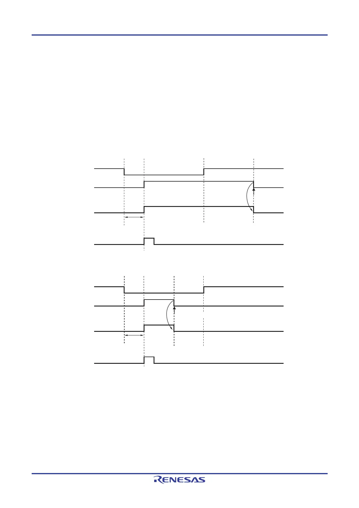
As shown in Figure 15-7, only one interrupt is generated each time a falling edge is input to one channel (when KREG
= 0), regardless of whether the KRFn bit is cleared before or after a rising edge is input.
Figure 15-7. Basic Operation of the INTKR Signal When the Key Interrupt Flag Is Used
(When KRMD = 1 and KREG = 0)
(a) When KRF0 is cleared after a rising edge is input to the KR0 pin
KR0
KRF0
Cleared by
software
INTKR
KRIF
Note
Delay
time
Clear
(b) When KRF0 is cleared before a rising edge is input to the KR0 pin
KR0
KRF0
INTKR
KRIF
Note
Delay
time
Clear
Cleared by software
Note Acknowledgment of vectored interrupt request or bit cleared by software

 Loading...


