RL78/G10 CHAPTER 12 SERIAL ARRAY UNIT
R01UH0384EJ0311 Rev. 3.11 289
Dec 22, 2016
12.3.5 Serial data register 0n (SDR0nH, SDR0nL)
The SDR0nH and SDR0nL registers are the transmit/receive data registers of channel n.
The SDR0nH and SDR0nL registers are set by an 8-bit memory manipulation instruction.
Reset signal generation clears the SDR0nH and SDR0nL registers to 00H.
The SDR0nH register is used as a register that sets the division ratio of the operating clock (f
MCK).
If the CCS0n bit of the SMR0nH register is cleared to 0, the clock set by dividing the operating clock by the SDR0nH
register is used as the transfer clock.
If the CCS0n bit of the SMR0nH register is set to 1, set the SDR0nH register to 00000000B. The input clock f
SCK from
the SCKp pin (slave transmission in the CSI mode) is used as the transfer clock.
The SDR0nH register is set by an 8-bit memory manipulation instruction when the operation is stopped (SE0n = 0).
Writing to the SDR0nH register is ignored when the operation is enabled (SE0n = 1), and 0 is always read from the
SDR0nH register.
The SDR0nL register functions as a transmit/receive buffer register. During reception, the parallel data converted by
the shift register is stored in the SDR0nL register. During transmission, the data to be transmitted to the shift register is set
to the SDR0nL register.
The SDR0nL register is set by an 8-bit memory manipulation instruction when the operation is enabled (SE0n = 1).
Writing to the SDR0nL register is prohibited when the operation is stopped (SE0n = 0).
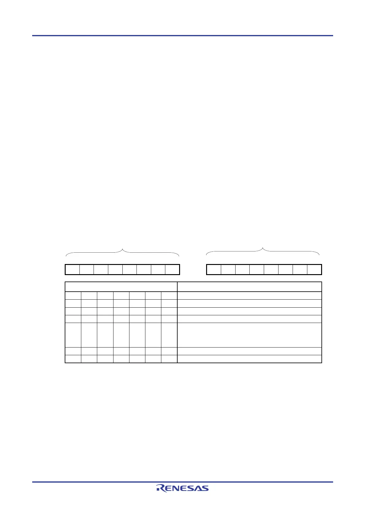
Figure 12-7. Format of Serial Data Register 0n (SDR0n)
Address: FFF11H (SDR00H) , FFF13H (SDR01H)
After reset: 00H R/W
Address: FFF10H (SDR00L) , FFF12H (SDR01L)
After reset: 00H R/W
Symbol 7 6 5 4 3 2 1 0 Symbol 7 6 5 4 3 2 1 0
SDR0nH 0 SDR0nL
SDR0nH[7:1] Transfer clock setting by dividing the operating clock (fMCK)
0 0 0 0 0 0 0 fMCK/2
0 0 0 0 0 0 1 fMCK/4
0 0 0 0 0 1 0 fMCK/6
0 0 0 0 0 1 1 fMCK/8
•
•
•
•
•
•
•
•
•
•
•
•
•
•
•
•
•
•
•
•
•
•
•
•
1 1 1 1 1 1 0 fMCK/254
1 1 1 1 1 1 1 fMCK/256
Cautions 1. Setting SDR0nH[7:1] = (0000000B, 0000001B) is prohibited when UART is used.
2. Setting SDR0nH[7:1] = 0000000B is prohibited when simplified I
2
C is used.
Remarks 1. For the function of the SDR0nL register, see 12.2 Configuration of Serial Array Unit.
2. n: Channel number (n = 0, 1)
Transmit/receive buffer register
Division ratio setting register

 Loading...


