RL78/G10 CHAPTER 12 SERIAL ARRAY UNIT
R01UH0384EJ0311 Rev. 3.11 294
Dec 22, 2016
12.3.9 Serial channel stop register 0 (ST0)
The ST0 register is a trigger register that is used to enable stopping communication/count for each channel.
When 1 is written to a bit of this register (ST0n), the corresponding bit (SE0n) of serial channel enable status register 0
(SE0) is cleared to 0 (operation is stopped). Because the ST0n bit is a trigger bit, it is cleared immediately when SE0n = 0.
The ST0 register is set by a 1-bit or 8-bit memory manipulation instruction.
Reset signal generation clears the ST0 register to 00H.
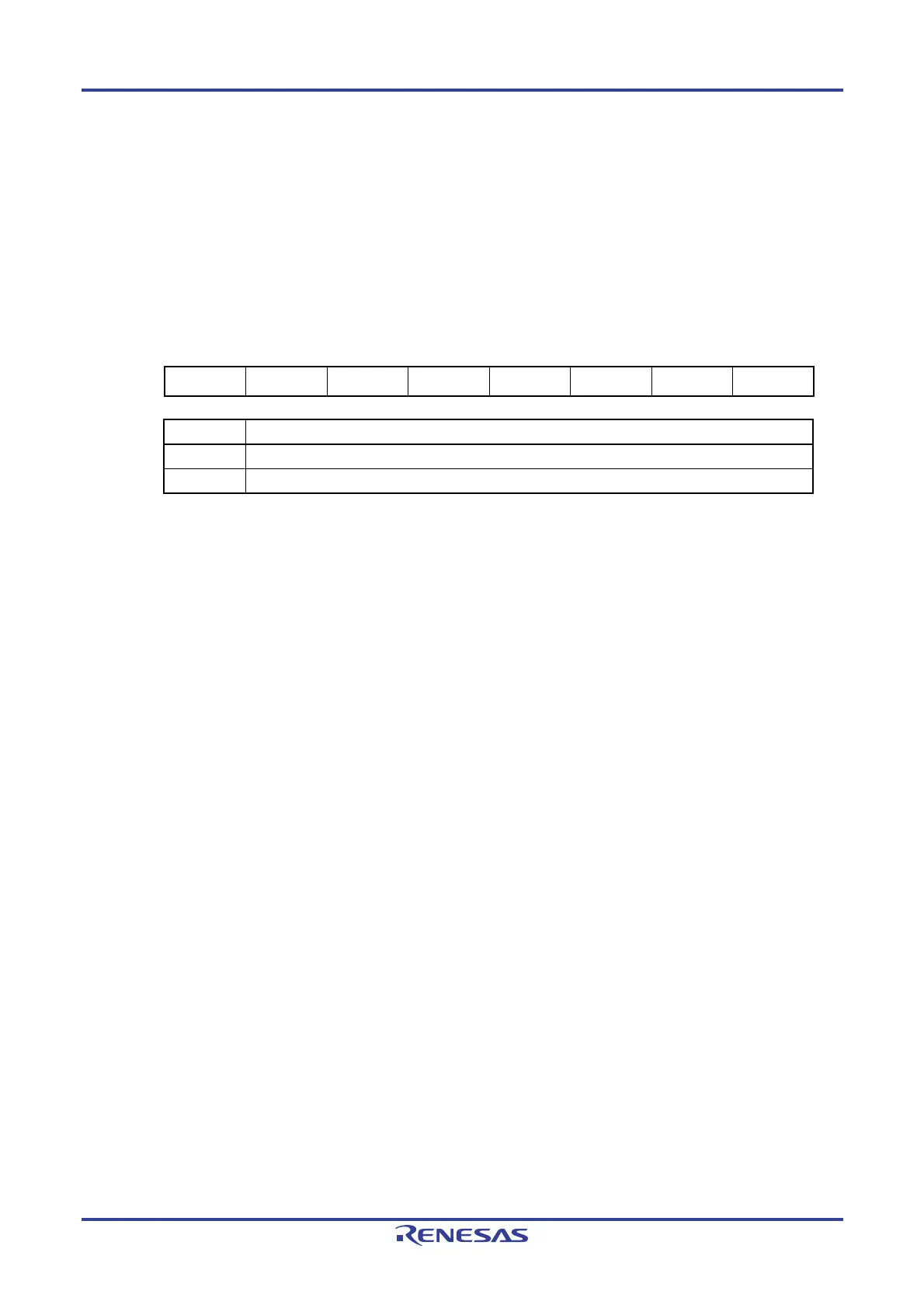
Figure 12-11. Format of Serial Channel Stop Register 0 (ST0)
Address: F0124H After reset: 00H R/W
Symbol
7 6 5 4 3 2 1 0
ST0 0 0 0 0 0 0 ST01 ST00
ST0n Operation stop trigger of channel n
0 No trigger operation
1
Clears the SE0n bit to 0 and stops the communication operation
Note
Note The control registers and the shift register, the SCK0n and SO0n pins, and the FEF0n, PEF0n,
and OVF0n flags retain their values.
Caution Be sure to clear bits 2 to 7 to 0.
Remarks 1. n: Channel number (n = 0, 1)
2. When the ST0 register is read, 00H is always read.

 Loading...


