RL78/G10 CHAPTER 16 STANDBY FUNCTION
R01UH0384EJ0311 Rev. 3.11 529
Dec 22, 2016
16.3.2 STOP mode
(1) STOP mode setting and operating statuses
The STOP mode is set by executing the STOP instruction.
Caution Because the interrupt request signal is used to clear the STOP mode, if the interrupt mask flag is 0
(the interrupt processing is enabled) and the interrupt request flag is 1 (the interrupt request signal is
generated), the STOP mode is immediately cleared if set when the STOP instruction is executed in
such a situation. Accordingly, once the STOP instruction is executed, the system returns to its
normal operating mode after the elapse of release time from the STOP mode.
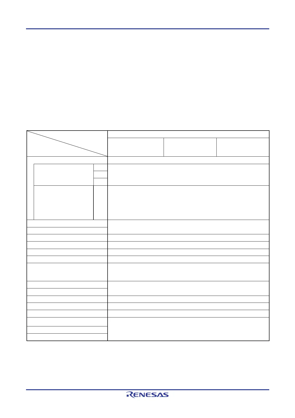
The operating statuses in the STOP mode are shown below.
Table 16-2. Operating Statuses in STOP Mode
STOP Mode Setting
Item
When STOP Instruction Is Executed While CPU Is Operating
When CPU Is Operating
on High-speed On-chip
Oscillator Clock (f
IH)
When CPU Is Operating
on X1 Clock (f
X)
When CPU Is Operating
on External Main System
Clock (f
EX)
System clock Clock supply to the CPU is stopped
Main system clock fIH Stopped
fX
fEX
Low Speed On-chip Oscillator
clock
fIL Set by bits 0 (WDSTBYON) and 4 (WDTON) of option byte (000C0H), and bit 4
(WUTMMCK0) of operation speed mode control register (OSMC)
• WUTMMCK0 = 1: Oscillates
• WUTMMCK0 = 0 and WDTON = 0: Stops
• WUTMMCK0 = 0, WDTON = 1, and WDSTBYON = 1: Oscillates
• WUTMMCK0 = 0, WDTON = 1, and WDSTBYON = 0: Stops
CPU Operation stopped
Code flash memory
RAM Operation stopped
Port (latch) Status before STOP mode was set is retained
Timer array unit Operation disabled
12-bit interval timer
Note
Operable
Watchdog timer Set by bit 0 (WDSTBYON) of option byte (000C0H)
• WDSTBYON = 0: Operation stopped
• WDSTBYON = 1: Operation continues
Clock output/buzzer output Operation disabled
A/D converter
Comparator
Note
Operable (only when the digital filter is not in use)
Serial array unit (SAU)
Operation disabled
Serial interface (IICA)
Note
Wakeup by address match operable
Selectable power-on-reset function Operable
External interrupt
Key interrupt function
Note 16-pin products only.
Remark Operation stopped: Operation is automatically stopped before switching to the STOP mode.
Operation disabled: Operation is stopped before switching to the STOP mode.
f
IH: High-speed on-chip oscillator clock
f
IL: Low-speed on-chip oscillator clock
fX: X1 clock
Note
f
EX: External main system clock
Note

 Loading...


