RL78/G10 CHAPTER 6 TIMER ARRAY UNIT
R01UH0384EJ0311 Rev. 3.11 147
Dec 22, 2016
6.6 Channel Output (TO0n pin) Control
6.6.1 TO0n pin output circuit configuration
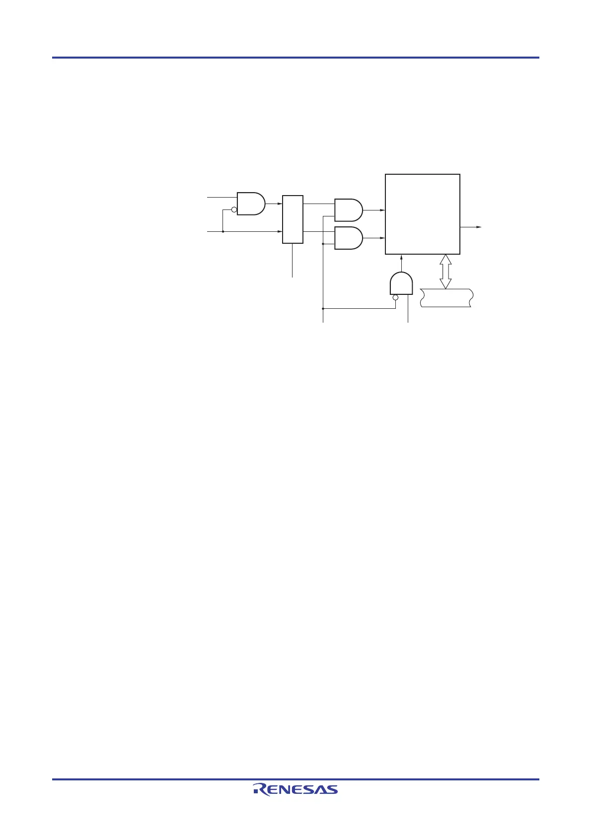
Figure 6-29. Output Circuit Configuration
Interrupt signal of the master channel
(INTTM0n)
TOL0n
TOM0n
TOE0n
<1>
<2>
TO0n write signal
TO0n pin
TO0n register
Set
<3>
<4>
Reset/toggle
Internal bus
Interrupt signal of the slave channel
(INTTM0p)
Controller
<5>
The following describes the TO0n pin output circuit.
<1> When TOM0n = 0 (master channel output mode), the set value of timer output level register 0 (TOL0) is
ignored and only INTTM0p (slave channel timer interrupt) is transmitted to timer output register 0 (TO0).
<2> When TOM0n = 1 (slave channel output mode), both INTTM0n (master channel timer interrupt) and INTTM0p
(slave channel timer interrupt) are transmitted to the TO0 register.
At this time, the TOL0 register becomes valid and the signals are controlled as follows:
When TOL0n = 0: Positive logic output (INTTM0n → set, INTTM0p → reset)
When TOL0n = 1: Negative logic output (INTTM0n → reset, INTTM0p → set)
When INTTM0n and INTTM0p are simultaneously generated, (0% output of PWM), INTTM0p (reset signal)
takes priority, and INTTM0n (set signal) is masked.
<3> While timer output is enabled (TOE0n = 1), INTTM0n (master channel timer interrupt) and INTTM0p (slave
channel timer interrupt) are transmitted to the TO0 register. Writing to the TO0 register (TO0n write signal)
becomes invalid.
When TOE0n = 1, the TO0n pin output never changes with signals other than interrupt signals.
To initialize the TO0n pin output level, it is necessary to set timer operation is stopped (TOE0n = 0) and to
write a value to the TO0 register.
<4> While timer output is disabled (TOE0n = 0), writing to the TO0n bit to the target channel (TO0n write signal)
becomes valid. When timer output is disabled (TOE0n = 0), neither INTTM0n (master channel timer interrupt)
nor INTTM0p (slave channel timer interrupt) is transmitted to the TO0 register.
<5> The TO0 register can always be read, and the TO0n pin output level can be checked.
Remark n: Master channel number
n = 0 (for 10-pin products); n = 0, 2 (for 16-pin products)
p: Slave channel number
n < p ≤ 3

 Loading...


