RL78/G10 CHAPTER 5 CLOCK GENERATOR
R01UH0384EJ0311 Rev. 3.11 95
Dec 22, 2016
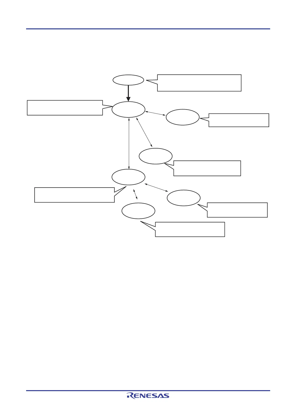
5.6.3 CPU clock status transition diagram
Figure 5-13 shows the CPU clock status transition diagram of this product.
Figure 5-13. CPU Clock Status Transition Diagram
High-speed on-chip oscillator: Woken up
X1 oscillation/EXCLK input: Stops (input port mode)
High-speed on-chip oscillator: Operating
X1 oscillation/EXCLK input: Selectable by CPU
High-speed on-chip oscillator: Selectable by CPU
X1 oscillation/EXCLK input: Operating
Power ON
(A)
(B)
CPU: Operating
high-speed on-chip
oscillator
(C)
(E)
CPU: High-speed
on-chip oscillator
=> STOP
CPU: High-speed
on-chip oscillator
=> HALT
CPU: X1 oscillation/
EXCLK input
=> HALT
CPU: Operating
with X1 oscillation or
EXCLK input
High-speed on-chip oscillator: Stops
X1 oscillation/EXCLK input: Stops
High-speed on-chip oscillator: Stops
X1 oscillation/EXCLK input: Stops
High-speed on-chip oscillator: Operating
X1 oscillation/EXCLK input: Oscillatable
High-speed on-chip oscillator: Oscillatable
X1 oscillation/EXCLK input: Operating
CPU: X1
oscillation/EXCLK
input => STOP
(F)
(D)
V
DD
being greater than the detection voltage for the SPOR
circuit and release from the reset state due to any reset source.

 Loading...


