RL78/G10 CHAPTER 11 COMPARATOR
R01UH0384EJ0311 Rev. 3.11 268
Dec 22, 2016
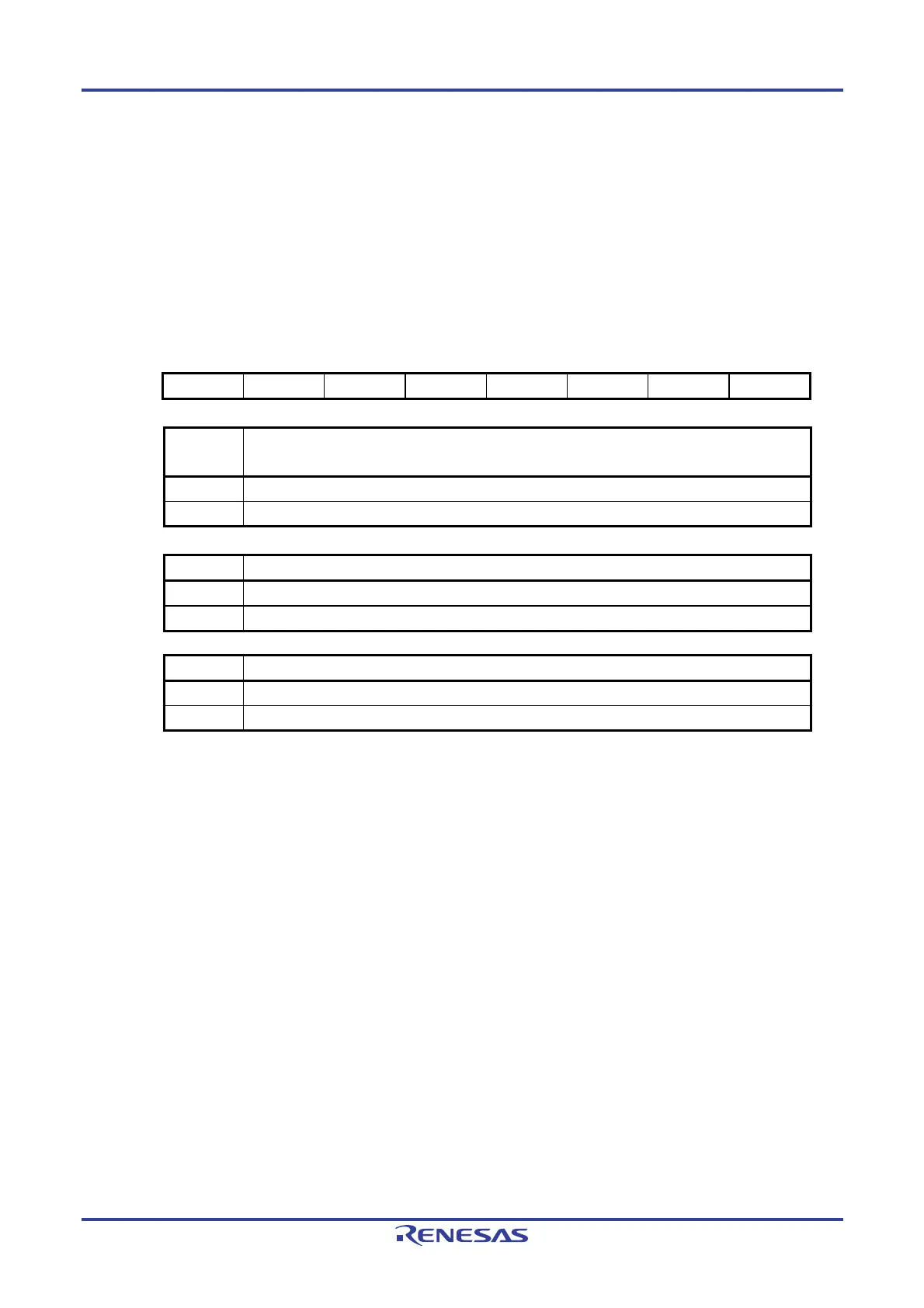
11.3.2 Comparator Mode Setting Register (COMPMDR)
This register selects the comparator reference voltage, starts/stops the comparison operation, and indicates the
comparison result state.
The COMPMDR register can be set by a 1-bit or 8-bit memory manipulation instruction. Note that the C0MON bit can
only be read.
Reset signal generation clears this register to 00H.
Figure 11-3. Format of Comparator Mode Setting Register (COMPMDR)
Address: FFF60H After reset: 00H R/W
Note 1
Symbol 7 6 5 4 <3> 2 1 <0>
COMPMDR 0 0 0 0 C0MON C0VRF 0 C0ENB
C0MON
Note 2
Comparator 0 monitor flag
0 IVCMP0 < comparator 0 reference voltage
1 IVCMP0 > comparator 0 reference voltage
C0VRF Comparator 0 reference voltage selection
0 Supplied from the IVREF0 pin.
1 Supplied from the internal reference voltage (0.815 V (typ.))
Note 3
C0ENB Comparator 0 operation control
0 Comparator 0 operation disabled
1 Comparator 0 operation enabled
Notes 1. Bit 3 is a read-only bit.
2. After the comparator 0 operation is enabled (C0ENB = 1), the IVREF0 pin state can be read
from the C0MON bit setting. When the comparator 0 operation is then disabled (C0ENB = 0),
the C0MON bit value is undefined.
3. When the internal reference voltage (0.815 V (typ.)) is selected as the comparator 0 reference
voltage, the internal reference voltage cannot be selected for the A/D converter.
 Loading...


