RL78/G10 CHAPTER 6 TIMER ARRAY UNIT
R01UH0384EJ0311 Rev. 3.11 113
Dec 22, 2016
6.2.1 Timer counter register 0n (TCR0n)
TCR0n register consists of two 8-bit read-only registers (TCR0nH and TCR0nL) and is used to count clocks (f
TCLK).
When data is read from the TCR0n register, the TCR0nH and TCR0nL registers must be accessed consecutively.
The value of this counter is incremented or decremented in synchronization with the rising edge of a count clock (f
TCLK).
Whether the counter is incremented or decremented depends on the operation mode that is selected by the MD0n3 to
MD0n0 bits of timer mode register 0n (TMR0n) (refer to 6.3.3 Timer mode register 0n (TMR0n)).
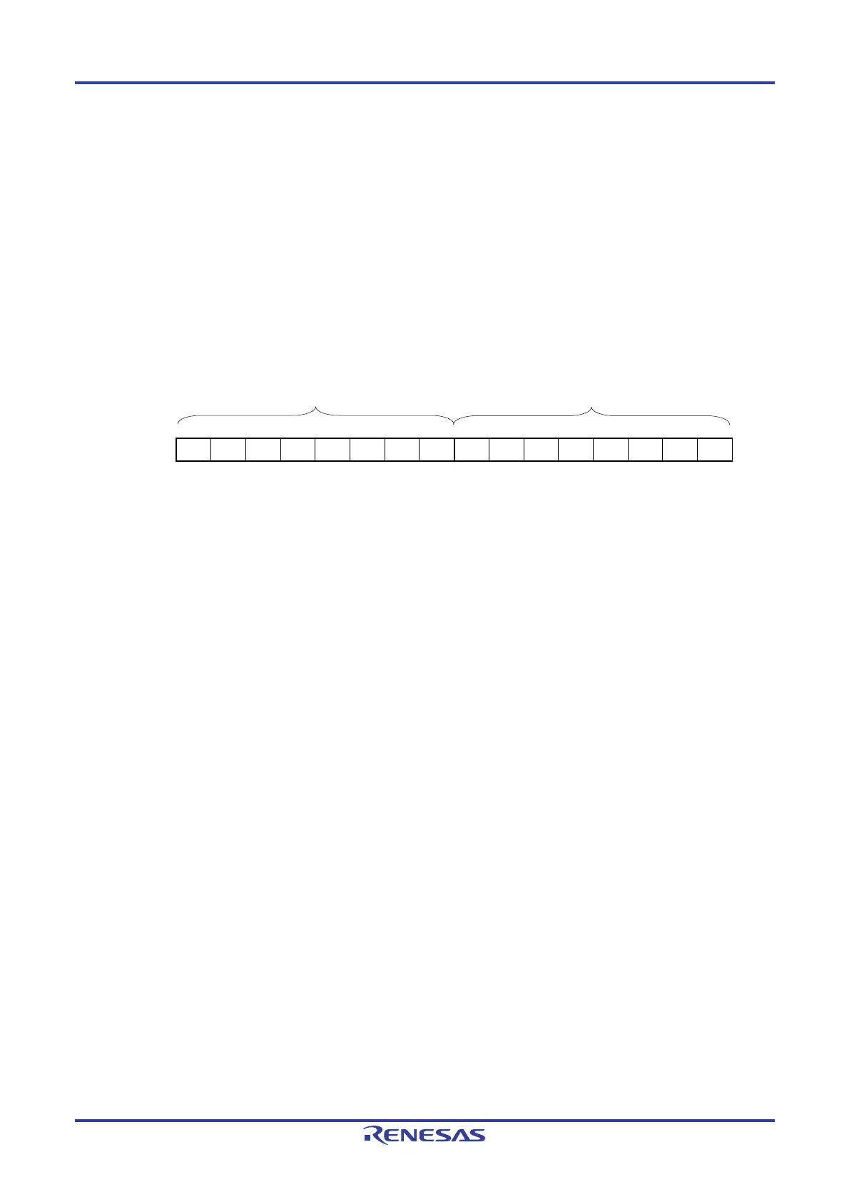
Figure 6-3. Format of Timer Counter Register 0n (TCR0n) (n = 0 to 3)
Address: F0180H (TCR00L), F0181H (TCR00H) After reset: FFH R
: F0182H (TCR01L), F0183H (TCR01H)
: F0184H (TCR02L), F0185H (TCR02H)
: F0186H (TCR03L), F0187H (TCR03H)
15 14 13 12 11 10 9 8 7 6 5 4 3 2 1 0
TCR0n
Remark n: Channel number
n = 0, 1 (for 10-pin products); n = 0 to 3 (for 16-pin products)
Reading from the TCR0nH and TCR0nL registers must be performed successively, in order of the TCR0nL register and
the TCR0nH register. If data are read from TCR0nL between the successive read, reading is not performed correctly.
Caution Consecutive reading from the TCR0nH and TCR0nL registers must be performed in the state
where an interrupt is disabled by the DI instruction.
The count value can be read by reading timer counter register 0n (TCR0n).
The count value is set to FFFFH in the following cases.
• When the reset signal is generated
• When the TAU0EN bit of peripheral enable register 0 (PER0) is cleared
• When counting of the slave channel has been completed in the PWM output mode
• When counting has been completed in the delay count mode
• When counting of the master/slave channel has been completed in the one-shot pulse output mode
• When counting of the slave channel has been completed in the multiple PWM output mode
Note
The count value is cleared to 0000H in the following cases.
• When the start trigger is input in the capture mode
• When capturing has been completed in the capture mode
Note 16-pin products only.
Cautions 1. The count value is not captured to timer data register 0n (TDR0n) even when the TCR0n
register is read.
2. When channels 1 and 3 are used in 8-bit timer mode (SPLIT = 1), it is prohibited to read the
TCR01H and TDR01H registers or the TCR03H and TDR03H registers.
TCR0nH
TCR0nL

 Loading...


