RL78/G10 CHAPTER 13 SERIAL INTERFACE IICA
R01UH0384EJ0311 Rev. 3.11 415
Dec 22, 2016
13.3.1 Peripheral enable register 0 (PER0)
This register is used to enable or disable supplying the clock to the peripheral hardware. Clock supply to a hardware
macro that is not used is stopped in order to reduce the power consumption and noise.
When serial interface IICA is used, be sure to set bit 4 (IICA0EN) of this register to 1.
The PER0 register can be set by a 1-bit or 8-bit memory manipulation instruction.
Reset signal generation clears this register to 00H.
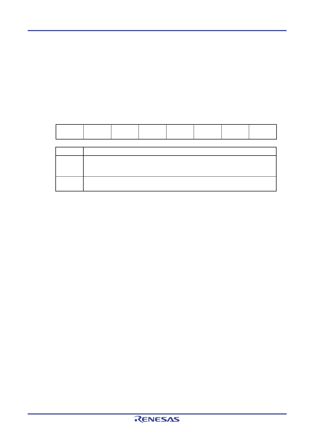
Figure 13-5. Format of Peripheral Enable Register 0 (PER0)
Address: F00F0H After reset: 00H R/W
Symbol <7> <6> <5> <4> <3> <2> 1 <0>
PER0
TMKAEN
Note
CMPEN
Note
ADCEN IICA0EN
Note
0 SAU0EN 0 TAU0EN
IICA0EN Control of serial interface IICA input clock supply
0
Stops input clock supply.
• SFR used by serial interface IICA cannot be written.
• Serial interface IICA is in the reset status.
1
Enables input clock supply.
• SFR used by serial interface IICA can be read/written.
Note 16-pin products only
Cautions 1. When setting serial interface IICA, be sure to set the following registers first while the
IICA0EN bit is set to 1. If IICA0EN = 0, the control registers of serial interface IICA are set
to their initial values, and writing to them is ignored (except for port mode register 0
(PM0), port register 0 (P0), port output mode register 0 (POM0), and port mode control
register 0 (PMC0)).
• IICA control register 00 (IICCTL00)
• IICA flag register 0 (IICF0)
• IICA status register 0 (IICS0)
• IICA control register 01 (IICCTL01)
• IICA low-level width setting register 0 (IICWL0)
• IICA high-level width setting register 0 (IICWH0)
2. Be sure to clear the following bits to 0.
10-pin products: Bits 1, 3, 4, 6, and 7
16-pin products: Bits 1 and 3
13.3.2 IICA control register 00 (IICCTL00)
This register is used to enable/stop I
2
C operations, set wait timing, and set other I
2
C operations.
The IICCTL00 register can be set by a 1-bit or 8-bit memory manipulation instruction. However, set the SPIE0, WTIM0,
and ACKE0 bits while IICE0 = 0 or during the wait period. These bits can be set at the same time when the IICE0 bit is set
from “0” to “1”.
Reset signal generation clears this register to 00H.

 Loading...


