RL78/G10 CHAPTER 5 CLOCK GENERATOR
R01UH0384EJ0311 Rev. 3.11 81
Dec 22, 2016
5.3.3 Clock operation status control register (CSC)
This register is used to control the operations of the high-speed system clock and high-speed on-chip oscillator clock,
(except the low-speed on-chip oscillator clock).
The CSC register can be set by a 1-bit or 8-bit memory manipulation instruction.
Reset signal generation sets this register to 80H.
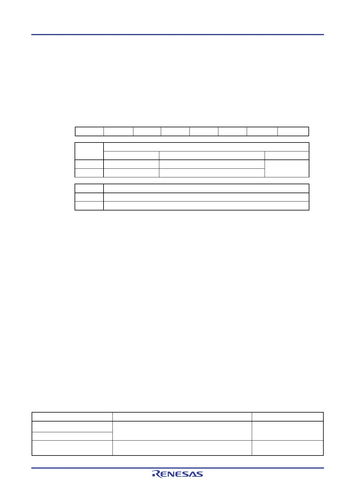
Figure 5-4. Format of Clock Operation Status Control Register (CSC)
Address: FFFA1H After reset: 80H R/W
Symbol <7> 6 5 4 3 2 1 <0>
CSC MSTOP 0 0 0 0 0 0 HIOSTOP
MSTOP High-speed system clock operation control
X1 oscillation mode External clock input mode Input port mode
0 X1 oscillator operating An external clock from the EXCLK pin enabled Input port
1 X1 oscillator stopped An external clock from the EXCLK pin disabled
HIOSTOP High-speed on-chip oscillator clock operation control
0 High-speed on-chip oscillator clock operating
1 High-speed on-chip oscillator clock stopped
Cautions 1. After reset release, set the clock operation mode control register (CMC) before
setting the CSC register.
2. Switch the operation mode of the X1/X2 pins only when MSTOP = 1.
3. When setting MSTOP bit to 0, switch the X1/X2 pins to the f
X operation mode
beforehand. Setting the MSTOP flag is disabled in the input port mode.
4. Set the oscillation stabilization time select register (OSTS) before setting the
MSTOP bit to 0 after releasing reset. Note that if the OSTS register is being
used with its default settings, the OSTS register is not required to be set here.
5. To start X1 oscillation as set by the MSTOP bit, check the oscillation
stabilization time of the X1 clock by using the oscillation stabilization time
counter status register (OSTC).
6. When setting MSTOP bit to 1 in the f
X operation mode, make sure that MCS in
the CKC register is 0 beforehand.
7. In the f
X operation mode, writing to the MSTOP flag is enabled but the stop
control is not performed.
8. Do not stop the clock selected for the CPU peripheral hardware clock (f
CLK) with
the CSC register.
9. The setting of the flags of the register to stop clock oscillation and the condition
before clock oscillation is to be stopped are as Table 5-2.
Before stopping the clock oscillation, check the conditions before the clock
oscillation is stopped.
Table 5-2. Condition Before Stopping Clock Oscillation and Flag Setting
Clock Condition Before Stopping Clock Setting of CSC Register Flags
X1 clock
CPU and peripheral hardware clocks operate with a high-speed
on-chip oscillator clock. (MCS = 0)
MSTOP = 1
External main system clock
High-speed on-chip oscillator clock
CPU and peripheral hardware clocks operate with a high-speed
system clock.(MCS = 1)
HIOSTOP = 1

 Loading...


