RL78/G10 CHAPTER 10 A/D CONVERTER
R01UH0384EJ0311 Rev. 3.11 251
Dec 22, 2016
10.3.6 Analog input channel specification register (ADS)
This register specifies the input channel of the analog voltage to be A/D converted.
The ADS register can be set by a 1-bit or 8-bit memory manipulation instruction.
Reset signal generation clears this register to 00H.
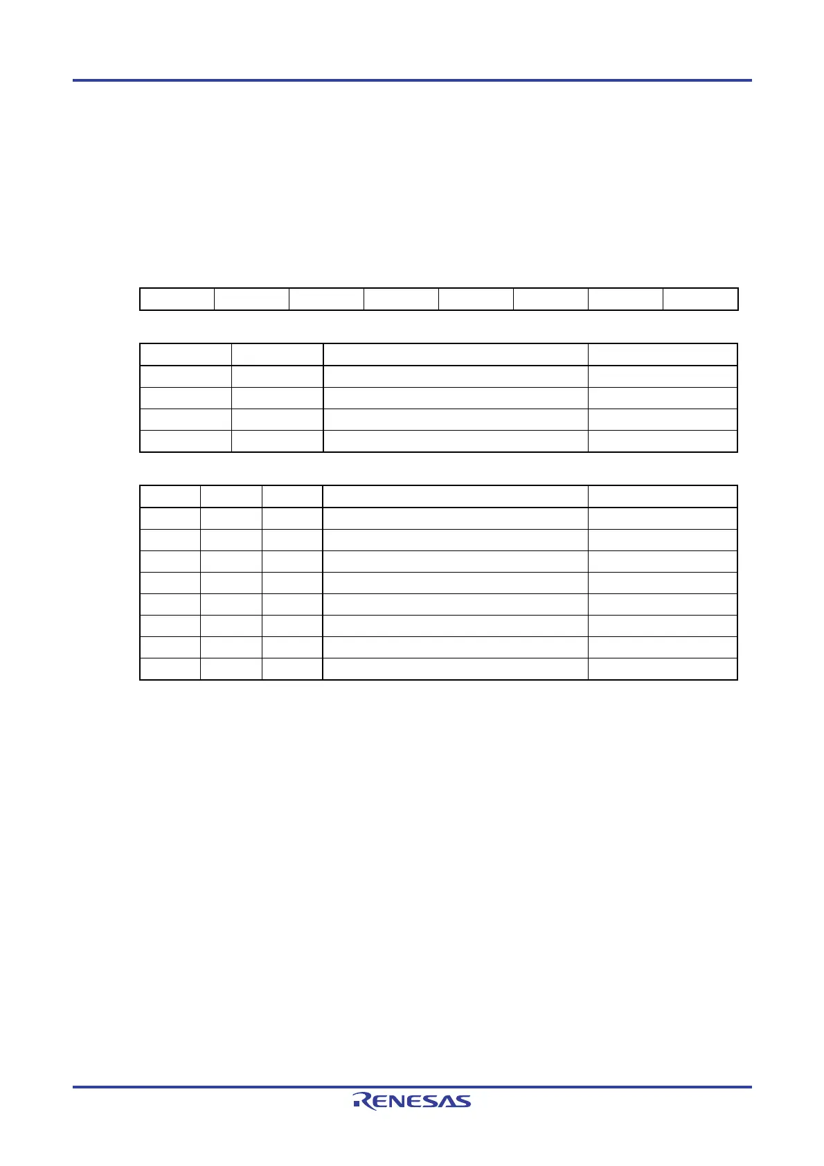
Figure 10-10. Format of Analog Input Channel Specification Register (ADS)
Address: FFF31H After reset: 00H R/W
Symbol 7 6 5 4 3 2 1 0
ADS 0 0 0 0 0 ADS2
Note 1
ADS1 ADS0
10-pin products
ADS1 ADS0 Target of A/D conversion Analog input pin
0 0 ANI0 P01/ANI0 pin
0 1 ANI1 P02/ANI1 pin
1 0 ANI2 P03/ANI2 pin
1 1 ANI3 P04/ANI3 pin
16-pin products
ADS2 ADS1 ADS0 Target of A/D conversion Analog input pin
0 0 0 ANI0 P01/ANI0 pin
0 0 1 ANI1 P02/ANI1 pin
0 1 0 ANI2 P03/ANI2 pin
0 1 1 ANI3 P04/ANI3 pin
1 0 0 ANI4 P05/ANI4 pin
1 0 1 ANI5 P06/ANI5 pin
1 1 0 ANI6 P07/ANI6 pin
1 1 1 Internal reference voltage (0.815 V (typ.))
Note 2
−
Notes 1. 16-pin products only.
2. When the internal reference voltage is selected as the target for conversion by the A/D converter,
be sure to clear the LV0 bit in the A/D converter mode register 0 (ADM0) to 0.
Cautions 1. Rewrite the ADS register in the conversion standby status (ADCS = 0, ADCE = 1) or in the
conversion stopped status (ADCS = 0, ADCE = 0).
2. Set the port used as an analog input port to the input mode by using the port mode
register 0 (PM0) and to the analog input by using the port mode control register 0 (PMC0).
Do not set the pin that is set by port mode control register 0 (PMC0) as digital I/O by the
ADS register.
3. The internal reference voltage cannot be used for the A/D converter and comparator
simultaneously. When the internal reference voltage is selected as the target for
conversion by the A/D converter (ADS2 to ADS0 = 111B), it cannot be selected as the
reference voltage of the comparator.
4. Be sure to clear the following bits to 0.
10-pin products: Bits 2 to 7
16-pin products: Bits 3 to 7

 Loading...


