RL78/G10 CHAPTER 10 A/D CONVERTER
R01UH0384EJ0311 Rev. 3.11 260
Dec 22, 2016
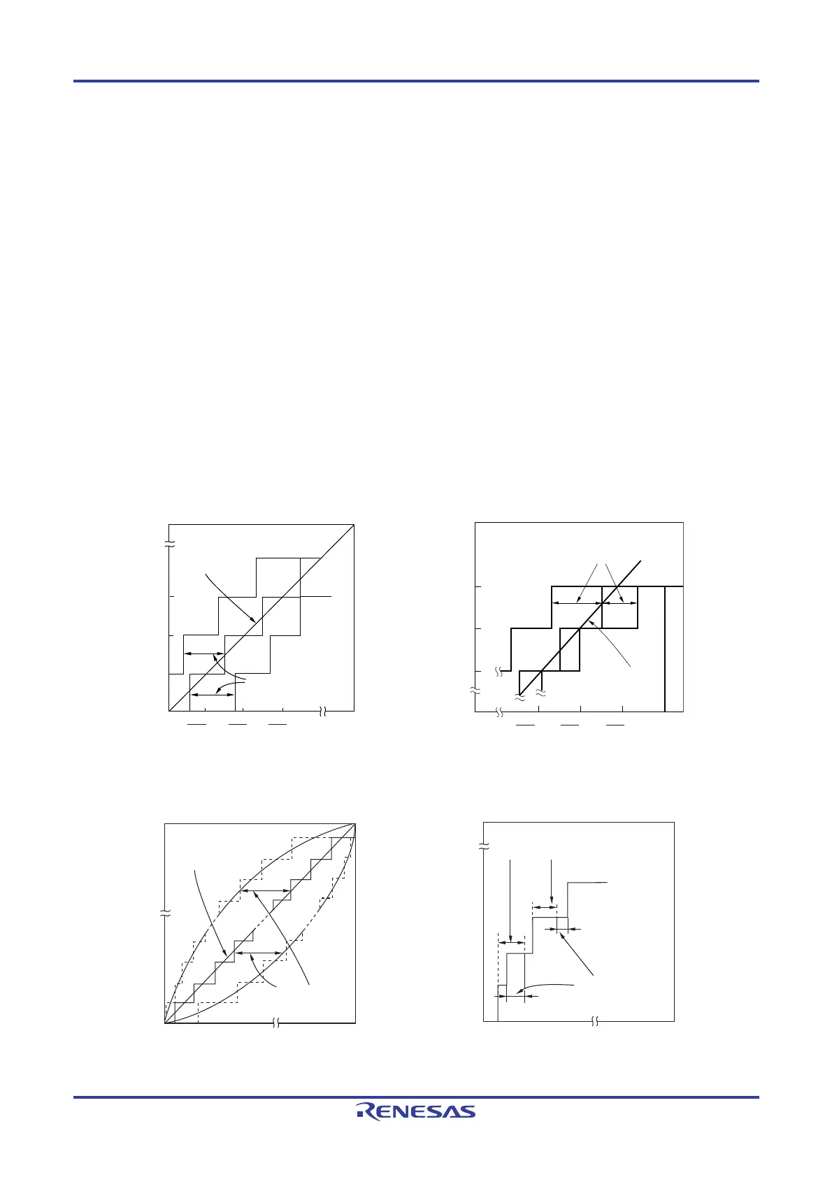
10.8.4 Zero-scale error
This shows the difference between the actual measurement value of the analog input voltage and the theoretical value
(1/2LSB) when the digital output changes from 0......000 to 0......001.
If the actual measurement value is greater than the theoretical value, it shows the difference between the actual
measurement value of the analog input voltage and the theoretical value (3/2LSB) when the digital output changes from
0……001 to 0……010.
10.8.5 Full-scale error
This shows the difference between the actual measurement value of the analog input voltage and the theoretical value
(full-scale − 3/2LSB) when the digital output changes from 1......110 to 1......111.
10.8.6 Integral linearity error
This shows the degree to which the conversion characteristics deviate from the ideal linear relationship. It expresses
the maximum value of the difference between the actual measurement value and the ideal straight line when the zero-
scale error and full-scale error are 0.
10.8.7 Differential linearity error
While the ideal width of code output is 1LSB, this indicates the difference between the actual measurement value and
the ideal value.
Figure 10-19. Zero-Scale Error Figure 10-20. Full-Scale Error
1
1024
V
DD
2
1024
V
DD
3
1024
V
DD
V
DD
Analog input (V)
111
011
010
001
Zero-scale error
Ideal line
000
0
Digital output (Lower 3 bits)
VDD
1021
1024
1022
1024
1023
1024
Analog input (V)
111
110
101
000
0
Full-scale error
Ideal line
Digital output (Lower 3 bits)
VDD
VDD VDD
Figure 10-21. Integral Linearity Error Figure 10-22. Differential Linearity Error
0
VDD
Digital output
Analog input
Integral linearity
error
Ideal line
1
......
1
0
......
0
0
VDD
Digital output
Analog input
Differential
linearity error
1
......
1
0
......
0
Ideal 1LSB width

 Loading...


