RL78/G10 CHAPTER 12 SERIAL ARRAY UNIT
R01UH0384EJ0311 Rev. 3.11 293
Dec 22, 2016
12.3.8 Serial channel start register 0 (SS0)
The SS0 register is a trigger register that is used to enable communication/count for each channel.
When 1 is written to a bit of this register (SS0n), the corresponding bit (SE0n) of serial channel enable status register 0
(SE0) is set to 1 (operation is enabled). Because the SS0n bit is a trigger bit, it is cleared immediately when SE0n = 1.
The SS0 register can be set by an 8-bit memory manipulation instruction.
Reset signal generation clears the SS0 register to 00H.
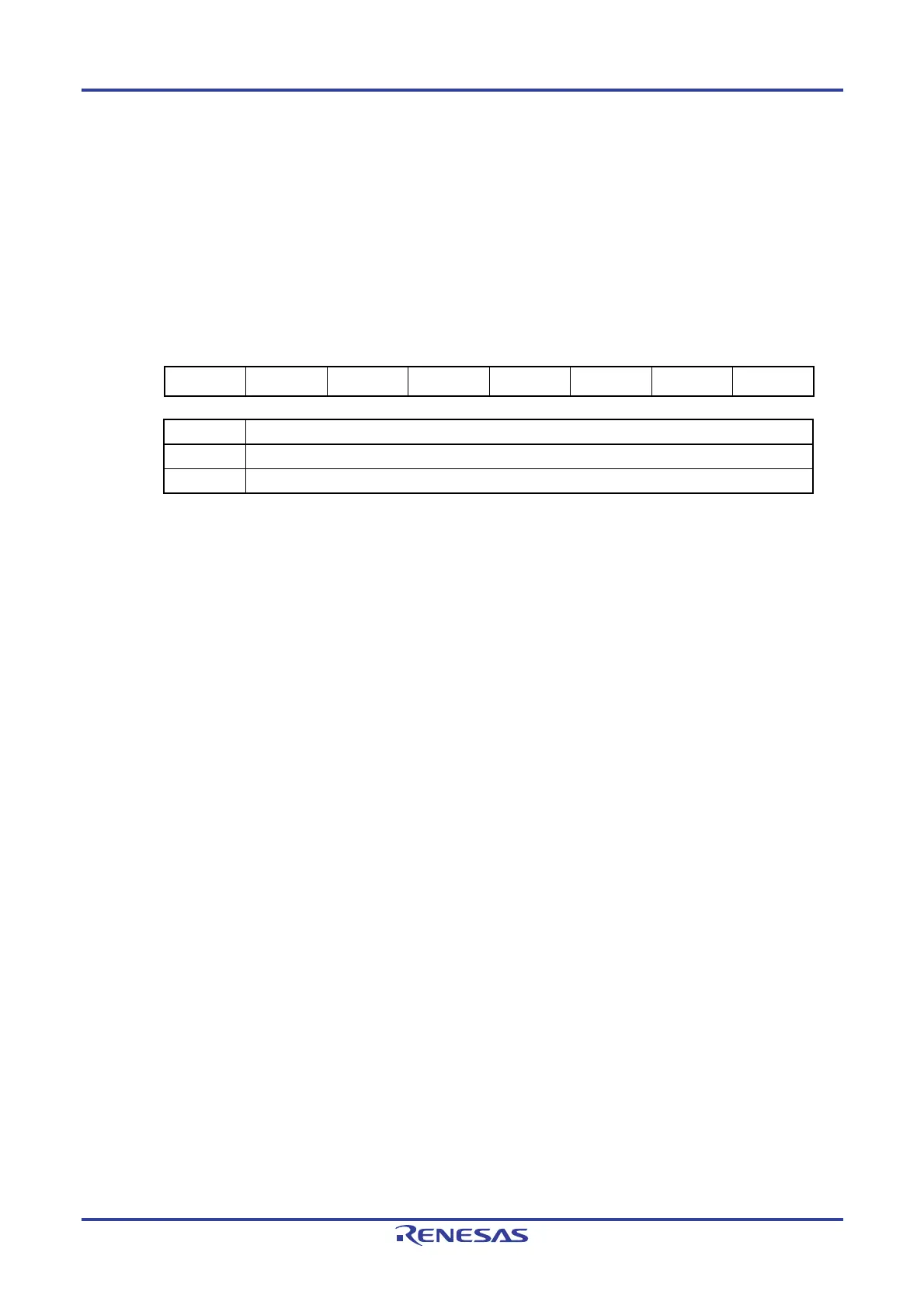
Figure 12-10. Format of Serial Channel Start Register 0 (SS0)
Address: F0122H (SS0) After reset: 00H R/W
Symbol
7 6 5 4 3 2 1 0
SS0 0 0 0 0 0 0 SS01 SS00
SS0n Operation start trigger of channel n
0 No trigger operation
1 Sets the SE0n bit to 1 and enters the communication wait status
Note
.
Note If SS0n is set to 1 during transfer operations, transfer stops and the interface enters the state of
waiting. At this time, the control registers and the shift register, the SCK0n and SO0n pins, and the
FEF0n, PEF0n, and OVF0n flags retain their values.
Cautions 1. Be sure to clear bits 2 to 7 to 0.
2. For the UART reception, set the RXE0n bit of SCR0nH register to 1, and then be sure to
set SS0n to 1 after 4 or more f
MCK clocks have elapsed.
Remarks 1. n: Channel number (n = 0, 1)
2. When the SS0 register is read, 00H is always read.

 Loading...


