RL78/G10 CHAPTER 6 TIMER ARRAY UNIT
R01UH0384EJ0311 Rev. 3.11 183
Dec 22, 2016
6.8.6 Operation as delay counter
It is possible to start counting down when the valid edge of the TI0n pin input is detected (an external event), and then
generate the interrupt request signal (INTTM0n) after any specified interval.
It can also generate INTTM0n at any interval by setting TS0n to 1 by software to start the count down during the period
of TE0n = 1.
The interrupt request signal (INTTM0n) generation period can be calculated by the following expression.
Generation period of interrupt request signal (INTTM0n) = Period of count clock × (Set value of TDR0n + 1)
Caution The TI0n pin input is sampled using the operating clock (f
MCK) selected with the CKS0n1 bit of
timer mode register 0n (TMR0n), so an error of one cycle of the operation clock (f
MCK) occurs.
When channel 1 or 3 is used as an 8-bit timer (SPLIT0n = 1), only the lower 8-bit timer can be used as the delay
counter.
Timer count register 0n (TCR0n) operates as a down counter in the one-count mode.
When the channel start trigger bit (TS0n) of timer channel start register 0 (TS0) is set to 1, the TE0n bit is set to 1 and
the TI0n pin input valid edge detection wait status is set.
Timer count register 0n (TCR0n) starts operating upon TI0n pin input valid edge detection and loads the value of timer
data register 0n (TDR0n). The TCR0n register counts down from the value of the TDR0n register it has loaded, in
synchronization with the count clock. When TCR0n = 0000H, it outputs INTTM0n and stops counting with TCR0n =
FFFFH until the next TI0n pin input valid edge is detected.
The TDR0n register can be rewritten at any time. The new value of the TDR0n register becomes valid from the next
period.
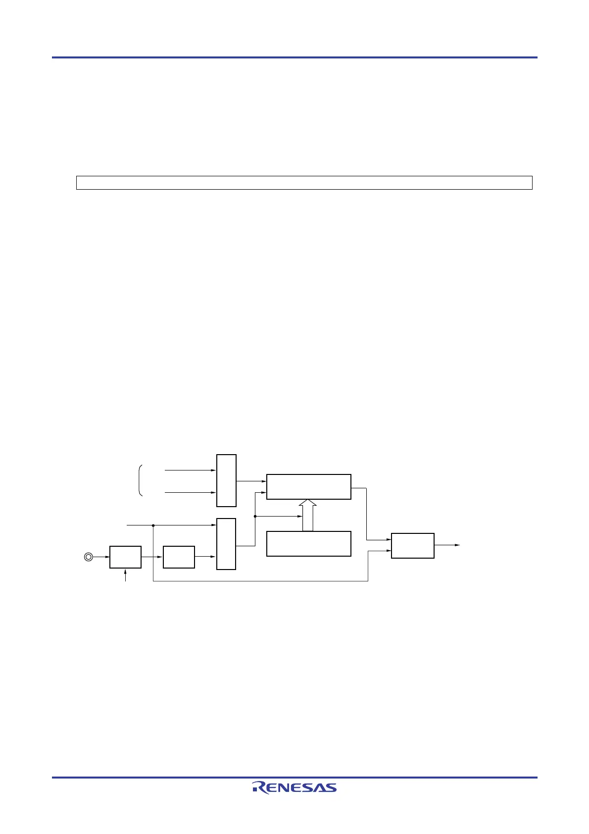
Figure 6-60. Block Diagram of Operation as Delay Counter
Interrupt signal
(INTTM0n)
Interrupt
controller
Operation clock
TI0n pin
CK00
CK01
TS0n
Clock selection
Trigger selection
Timer counter
register 0n (TCR0n)
Timer data
register 0n (TDR0n)
Edge
detection
Noise
filter
TNFEN0n
Remark n: Channel number
n = 0, 1 (for 10-pin products); n = 0 to 3 (for 16-pin products)

 Loading...


