RL78/G10 CHAPTER 12 SERIAL ARRAY UNIT
R01UH0384EJ0311 Rev. 3.11 376
Dec 22, 2016
12.6.2 UART reception
UART reception is an operation wherein the RL78/G10 asynchronously receives data from another device (start-stop
synchronization).
For UART reception, the odd-number channel of the two channels used for UART is used. The SMR register of both
the odd- and even-numbered channels must be set.
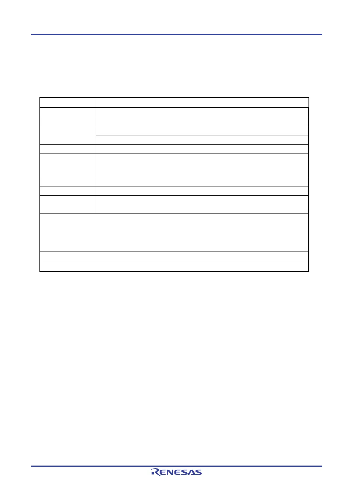
UART UART0
Target channel Channel 1 of SAU0
Pins used RxD0
Interrupt INTSR0
Transfer end interrupt only (setting the buffer empty interrupt is prohibited)
Error interrupt INTSRE0
Error detection flag
• Framing error detection flag (FEF0n)
• Parity error detection flag (PEF0n)
• Overrun error detection flag (OVF0n)
Transfer data length 7 or 8 bits (UART0 only)
Transfer rate
Note
Max. fMCK/6 [bps] (SDR0nH[7:1] = 2 or more), Min. fCLK/(2 × 2
15
× 128) [bps]
Data phase Non-inverted output (default: high level)
Inverted output (default: low level)
Parity bit
The following selectable
• No parity check
• No parity specified (0 parity)
• Appending even parity
• Appending odd parity
Stop Bit 1 bit check
Data direction MSB or LSB first
Note Use this operation within a range that satisfies the conditions above and the peripheral characteristics in the
electrical specifications (see CHAPTER 24 ELECTRICAL SPECIFICATIONS).
Remarks 1. fMCK: Operation clock frequency of target channel
f
CLK: System clock frequency
2. n: Channel number (n = 1)
 Loading...


