RL78/G10 CHAPTER 17 RESET FUNCTION
R01UH0384EJ0311 Rev. 3.11 539
Dec 22, 2016
17.3 Register for Confirming Reset Source
17.3.1 Reset Control Flag Register (RESF)
Many internal reset generation sources exist in the RL78 microcontroller. The reset control flag register (RESF) is used
to store which source has generated the reset request.
The RESF register can be read by an 8-bit memory manipulation instruction.
The external reset, a reset by the data retention lower limit voltage, and reading the RESF register clear TRAP,
WDTRF, and SPORF flags.
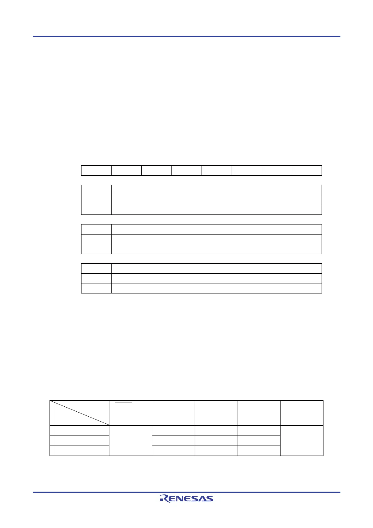
Figure 17-4. Format of Reset Control Flag Register (RESF)
ddress: FFFA8H After reset: Undefined
Note1
R
Symbol 7 6 5 4 3 2 1 0
RESF TRAP 0 0 WDTRF 0 0 0 SPORF
TRAP Internal reset request by execution of illegal instruction
Note 2
0 Internal reset request is not generated, or the RESF register is cleared.
1 Internal reset request is generated.
WDTRF Internal reset request by watchdog timer (WDT)
0 Internal reset request is not generated, or the RESF register is cleared.
1 Internal reset request is generated.
SPORF Internal reset request by selectable power-on reset (SPOR) circuit
0 Internal reset request is not generated, or the RESF register is cleared.
1 Internal reset request is generated.
Notes 1. The value after reset varies depending on the reset source.
2. The illegal instruction is generated when instruction code FFH is executed.
Reset by the illegal instruction execution not issued by emulation with the on-chip debug
emulator.
Caution Do not read data by a 1-bit memory manipulation instruction.
The status of the RESF register when a reset request is generated is shown in Table 17-3.
Table 17-3. RESF Register Status When Reset Request Is Generated
Reset Source
Flag
RESET Input
Reset by
Execution of
Illegal Instruction
Reset by
WDT
Reset by
SPOR
Reset by data
retention lower
limit voltage
TRAP bit Cleared (0) Set (1) Held Held Cleared (0)
WDTRF bit Held Set (1) Held
SPORF bit Held Held Set (1)
The RESF register is automatically cleared when it is read by an 8-bit memory manipulation instruction. Figure 17-5
shows the example of the procedure for checking the reset source.

 Loading...


