RL78/G10 CHAPTER 6 TIMER ARRAY UNIT
R01UH0384EJ0311 Rev. 3.11 128
Dec 22, 2016
6.3.7 Timer channel stop register 0 (TT0, TTH0 (8-bit mode))
The TT0 and TTH0 registers are trigger registers that are used to stop the counting operation of each channel.
When a bit of TT0 and TTH0 registers is set to 1, the corresponding bit of timer channel enable status register 0 (TE0,
TEH0) is cleared to 0. The TT0n and TTH0n bits are immediately cleared to 0 when operation is stopped (TE0n, TEH0n =
0), because they are trigger bits.
The TT0 and TTH0 registers can be set by a 1-bit or 8-bit memory manipulation instruction.
Reset signal generation clears TT0 and TTH0 registers to 00H.
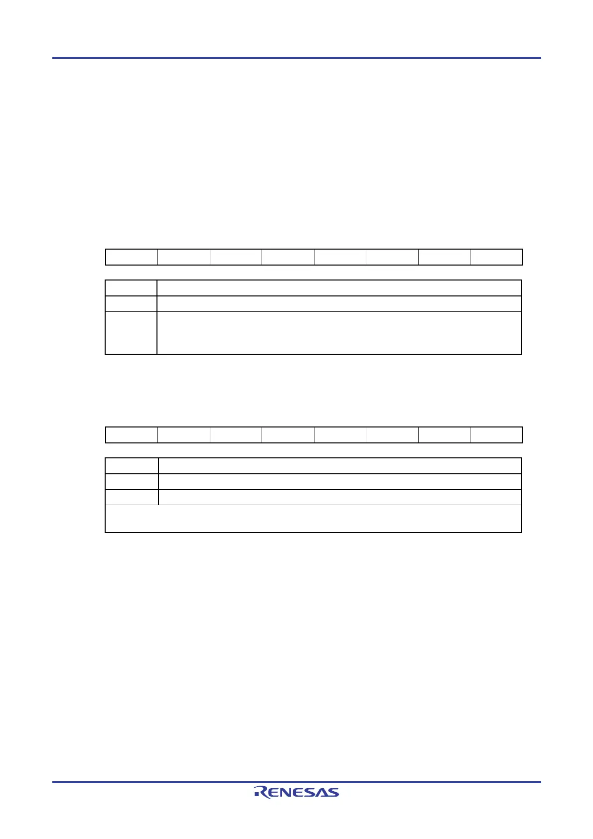
Figure 6-14. Format of Timer Channel Stop Register 0 (TT0)
Address: F01B4H After reset: 00H R/W
Symbol 7 6 5 4 3 2 1 0
TT0 0 0 0 0 TT03
Note
TT02
Note
TT01 TT00
TT0n Operation stop trigger of channel n (n = 0 to 3)
0 No trigger operation
1 TE0n is cleared to 0, and counting operation is stopped.
TT01 and TT03 bits are the trigger to stop operation of the lower 8-bit timer when channels 1 and 3
are in the 8-bit timer mode.
Figure 6-15. Format of Timer Channel Stop Register 0 (TTH0)
Address: F01B5H After reset: 00H R/W
Symbol 7 6 5 4 3 2 1 0
TTH0 0 0 0 0 TTH03
Note
0 TTH01 0
TTH0n Operation stop trigger of channel n (n = 1, 3)
0 No trigger operation
1 TEH0n is cleared to 0, and counting operation is stopped (stop trigger is generated).
This bit is the trigger to stop operation of the higher 8-bit timer when channels 1 and 3 are used in the 8-bit timer
mode.
Note 16-pin products only.
Caution Be sure to clear the following bits to 0.
TT0: Bits 2 to 7 in 10-pin products, bits 4 to 7 in 16-pin products
TTH0: Bits 0, 2 to 7 in 10-pin products, bits 0, 2, 4 to 7 in 16-pin products
Remark When the TT0 and TTH0 registers are read, 0 is always read.

 Loading...


