RL78/G10 CHAPTER 14 INTERRUPT FUNCTIONS
R01UH0384EJ0311 Rev. 3.11 502
Dec 22, 2016
14.3.1 Interrupt request flag registers (IF0L, IF0H, IF1L)
The interrupt request flags are set to 1 when the corresponding interrupt request is generated or an instruction is
executed. They are cleared to 0 when the interrupt request is acknowledged, a reset signal is generated, or an instruction
is executed.
When an interrupt is acknowledged, the interrupt request flag is automatically cleared and then the interrupt routine is
entered.
IF0L, IF0H, and IF1L registers can be set by a 1-bit or 8-bit memory manipulation instruction. Reset signal generation
clears these registers to 00H.
Remark If an instruction that writes data to this register is executed, the number of instruction execution clocks
increases by 2 clocks.
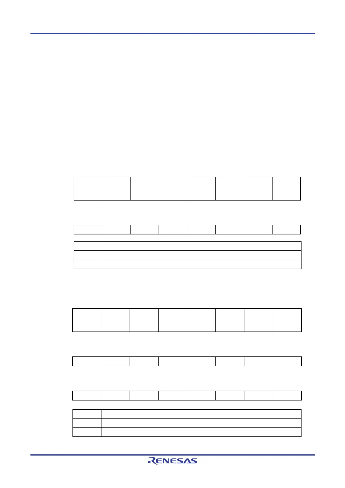
Figure 14-2. Format of Interrupt Request Flag Registers (IF0L, IF0H) (10-pin product)
ddress: FFFE0H After reset: 00H R/W
Symbol <7> <6> <5> <4> <3> <2> <1> <0>
IF0L TMIF00 TMIF01H SREIF0 SRIF0
STIF0
CSIIF00
IICIF00
PIF1 PIF0 WDTIIF
ddress: FFFE1H After reset: 00H R/W
Symbol 7 6 5 4 3 <2> <1> <0>
IF0H 0 0 0 0 0 KRIF ADIF TMIF01
XXIFXX Interrupt request flag
0 No interrupt request signal is generated
1 Interrupt request is generated, interrupt request status
Figure 14-3. Format of Interrupt Request Flag Registers (IF0L, IF0H, IF1L) (16-pin product)
Address: FFFE0H After reset: 00H R/W
Symbol <7> <6> <5> <4> <3> <2> <1> <0>
IF0L TMIF00 TMIF01H SREIF0
SRIF0
CSIIF01
STIF0
CSIIF00
IICIF00
PIF1 PIF0 WDTIIF
Address: FFFE1H After reset: 00H R/W
Symbol <7> <6> <5> <4> <3> <2> <1> <0>
IF0H TMIF02 IICAIF0 TMIF03H PIF3 PIF2 KRIF ADIF TMIF01
Address: FFFE2H After reset: 00H R/W
Symbol 7 6 5 4 3 <2> <1> <0>
IF1L 0 0 0 0 0 CMPIF0 ITIF TMIF03
XXIFXX Interrupt request flag
0 No interrupt request signal is generated
1 Interrupt request is generated, interrupt request status
(Cautions are listed on the next page.)
 Loading...


