RL78/G10 CHAPTER 20 FLASH MEMORY
R01UH0384EJ0311 Rev. 3.11 556
Dec 22, 2016
20.4.2 Flash memory programming mode
To rewrite the contents of the code flash memory by serial programming, the flash memory programming mode must be
entered.
<When performing serial programming by using the dedicated flash memory programmer>
Connect the RL78 microcontroller to the dedicated flash memory programmer. Communication from the dedicated flash
memory programmer is performed to automatically switch to the flash memory programming mode. The operating voltage
during the flash memory programming mode is 4.5 V to 5.5 V.
<When performing serial programming by using an external device (UART communication)>
Set the TOOL0 pin to the low level, and then cancel the reset (refer to Table 20-3). The flash memory programming
mode is then entered by following the procedures <1> to <4> shown in Figure 20-7.
The operating voltage during the flash memory programming mode is 4.5 V to 5.5 V.
Table 20-3. Relationship Between TOOL0 Pin and Operation Mode After Reset Release
TOOL0 Operation Mode
VDD Normal operation mode
0 V Flash memory programming mode
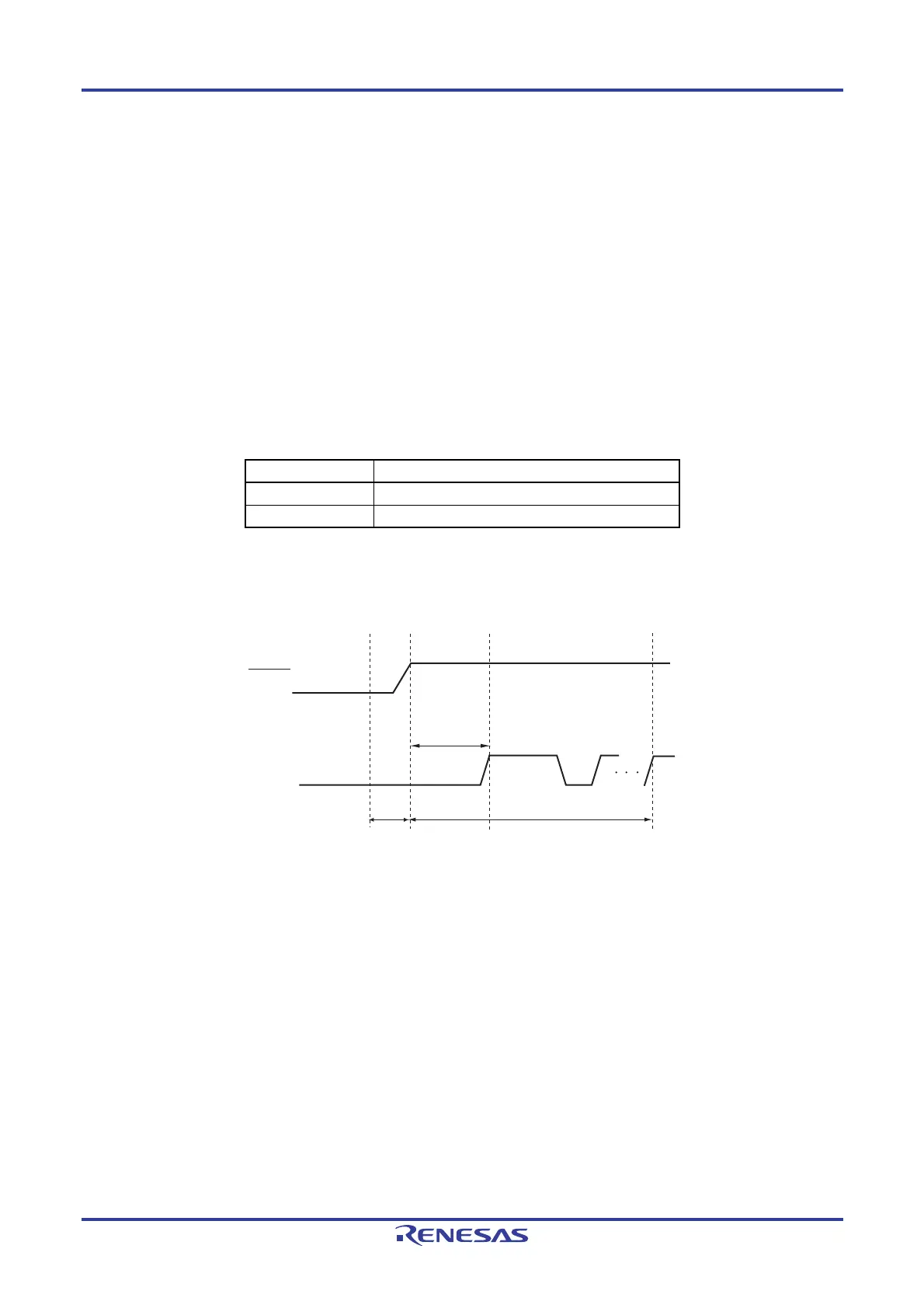
Figure 20-7. Entry to Flash Memory Programming Mode
RESET
TOOL0
<1>
<2>
<3>
t
SUINIT
tHD
t
SU
<4>
Mode setting
one-byte data
<1> The low level is input to the TOOL0 pin.
<2> The external reset ends (SPOR reset must end before the external reset ends.).
<3> The TOOL0 pin is set to the high level.
<4> Setting of entry to the flash memory programming mode by UART reception.
Remark t
SUINIT: The segment shows that it is necessary to finish specifying the initial communication settings within 100
ms from when the resets end.
tSU: How long from when the TOOL0 pin is placed at the low level until an external reset ends
t
HD: How long to keep the TOOL0 pin at the low level from when the external reset ends
For details, refer to 24.10
Timing of Entry to Flash Memory Programming Modes.

 Loading...


