RL78/G10 CHAPTER 14 INTERRUPT FUNCTIONS
R01UH0384EJ0311 Rev. 3.11 507
Dec 22, 2016
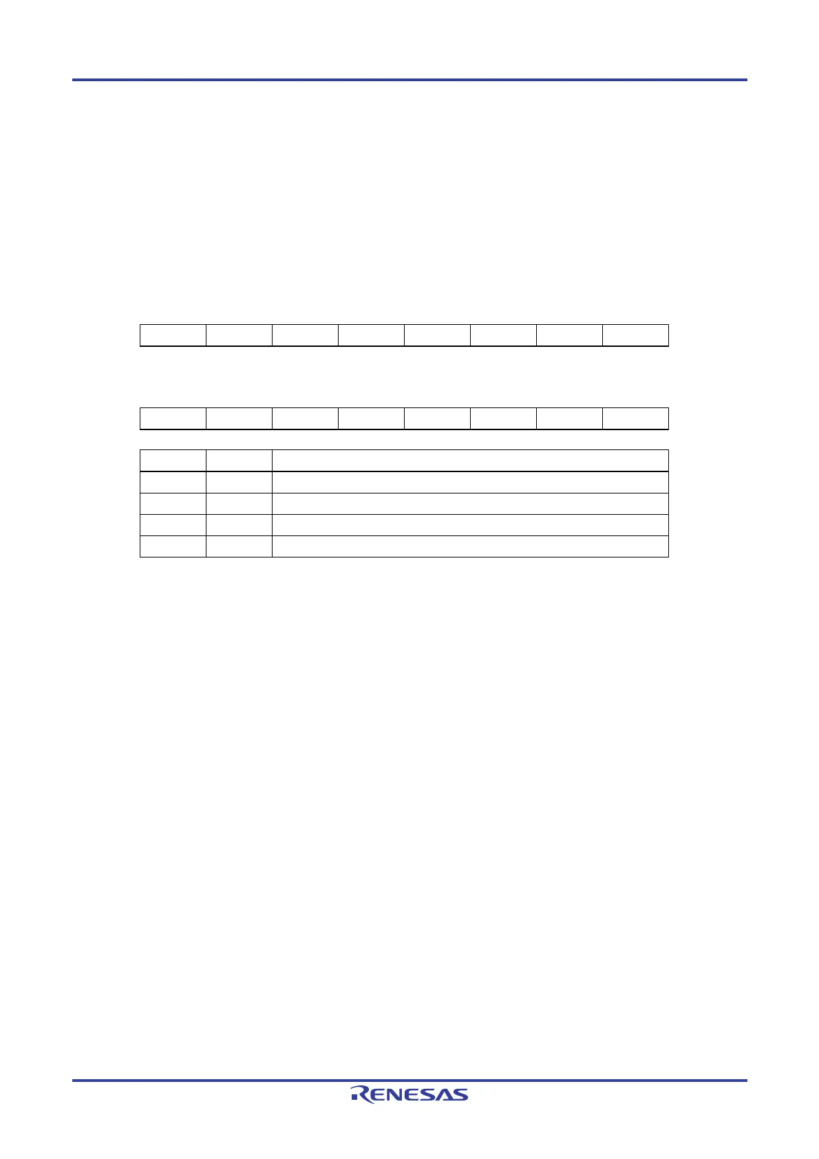
14.3.4 External interrupt rising edge enable register 0 (EGP0), external interrupt falling edge enable register 0
(EGN0)
These registers specify the valid edge for INTP0, INTP1, INTP2, and INTP3.
The EGP0 and EGN0 registers can be set by a 1-bit or 8-bit memory manipulation instruction.
Reset signal generation clears these registers to 00H.
Figure 14-8. Format of External Interrupt Rising Edge Enable Register 0 (EGP0) and External Interrupt Falling
Edge Enable Register 0 (EGN0)
ddress: FFF38H After reset: 00H R/W
Symbol 7 6 5 4 3 2 1 0
EGP0 0 0 0 0 EGP3
Note
EGP2
Note
EGP1 EGP0
ddress: FFF39H After reset: 00H R/W
Symbol 7 6 5 4 3 2 1 0
EGN0 0 0 0 0 EGN3
Note
EGN2
Note
EGN1 EGN0
EGPn EGNn INTPn pin valid edge selection (n = 0 to 3)
0 0 Edge detection disabled
0 1 Falling edge
1 0 Rising edge
1 1 Both rising and falling edges
Note 16-pin products only.
Caution When the input port pins used for the external interrupt functions are switched to the
output mode, the INTPn interrupt might be generated upon detection of a valid edge. When
switching the input port pins to the output mode, set the port mode register (PMxx) to 0
after disabling the edge detection (by setting EGPn and EGNn to 0).
Remarks 1. For the edge detection port, see 2.1 Port Functions.
2. n = 0 to 3

 Loading...


