RL78/G10 CHAPTER 4 PORT FUNCTIONS
R01UH0384EJ0311 Rev. 3.11 63
Dec 22, 2016
4.3.3 Pull-up resistor option registers 0, 4, 12 (PU0, PU4, PU12)
These registers specify whether the on-chip pull-up resistors are to be used or not. On-chip pull-up resistors can be
used in 1-bit units only for the bits that satisfy the following usage conditions for the pins to which the use of an on-chip
pull-up resistor has been specified in these registers.
Usage conditions of the on-chip pull-up resistor:
• PMmn = 1 (Input mode)
• PMCmn = 1 (Digital I/O)
• POM0n = 0 (Normal output mode)
On-chip pull-up resistors cannot be connected to bits set to output mode and bits used as alternate-function output pins,
regardless of the settings of these registers.
These registers can be set by a 1-bit or 8-bit memory manipulation instruction.
Reset signal generation sets PU4 to 01H, PU12 to 20H, and clears PU0 to 00H.
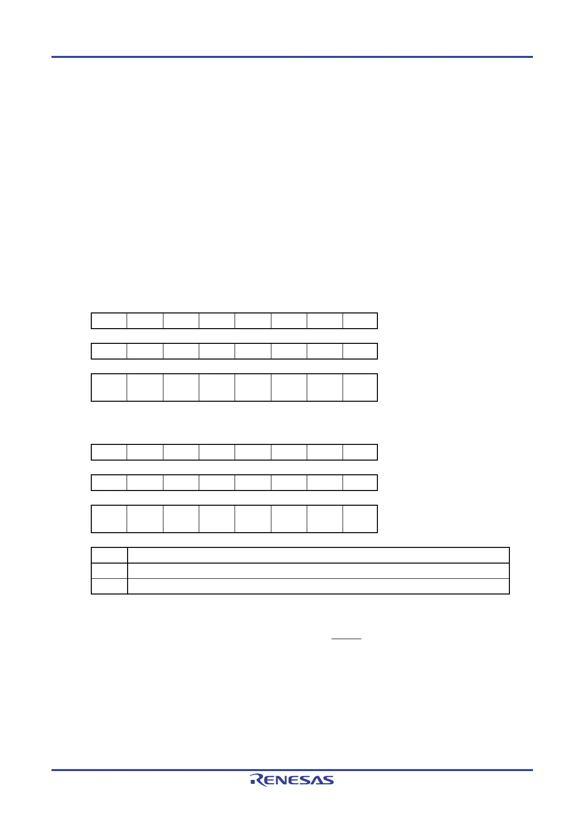
Figure 4-3. Format of Pull-up Resistor Option Registers 0, 4, 12 (PU0, PU4, PU12)
10-pin products
Symbol 7 6 5 4 3 2 1 0 Address After reset R/W
PU0 0 0 0 PU04 PU03 PU02 PU01 PU00 F0030H 00H R/W
PU4 0 0 0 0 0 0 0 PU40 F0034H 01H R/W
PU12 0 0
PU125
Note
0 0 0 0 0 F003CH 20H R/W
16-pin products
Symbol 7 6 5 4 3 2 1 0 Address After reset R/W
PU0 PU07 PU06 PU05 PU04 PU03 PU02 PU01 PU00 F0030H 00H R/W
PU4 0 0 0 0 0 0 PU41 PU40 F0034H 01H R/W
PU12 0 0
PU125
Note
0 0 0 0 0 F003CH 20H R/W
PUmn Pmn pin on-chip pull-up resistor selection
0 On-chip pull-up resistor not connected
1 On-chip pull-up resistor connected
m = 0, 4, 12; n = 0 to 7
Note This bit can be only manipulated when the P125/KR1 function is selected (PORTSELB = 0) (the on-chip
pull-up resistor is always valid (PU125 = 1) when the RESET input (PORTSELB = 1) is selected).
Caution Be sure to set bits that are not mounted to their initial values.

 Loading...


